Today I’m porting the official RPi Pico Debug probe to the Bus Pirate. There is another more advanced version I will do later, but I’ve ported this one before and it has less features to worry about.
It’s been updated to the new pirate-lib, but I’m having some trouble compiling. It seems to be trying to store some const variables in ram. Specifically the background image I suspect.
[build] Memory region         Used Size  Region Size  %age Used
[build]            FLASH:       60436 B         2 MB      2.88%
[build]              RAM:      150748 B       256 KB     57.51%
[build]        SCRATCH_X:          2 KB         4 KB     50.00%
[build]        SCRATCH_Y:          0 GB         4 KB      0.00%
When I disable the function that draws the background on the LCD.
Not that this would change this firmware, but for future BP designs…
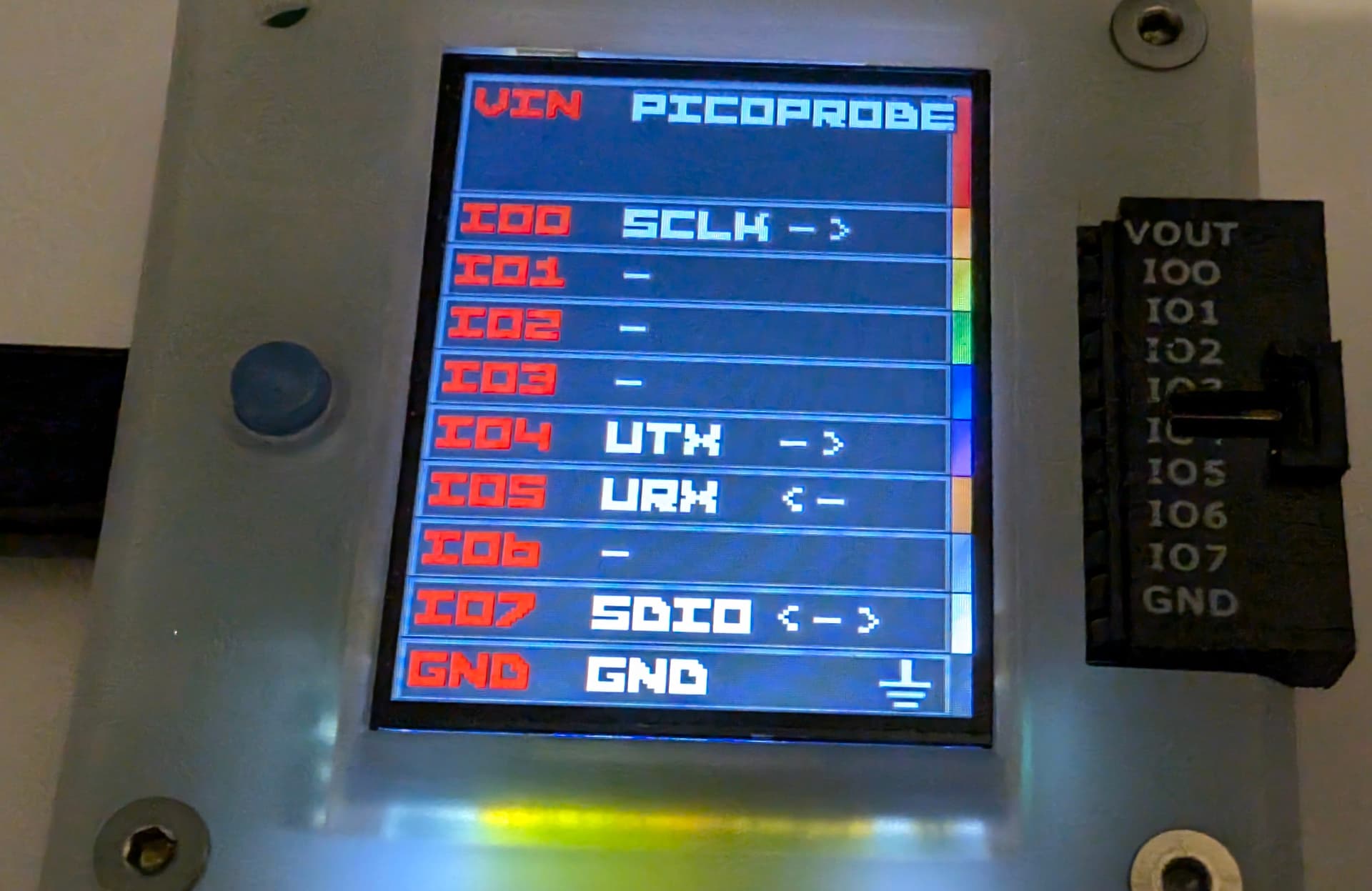
Does this mean that the pins used will change, depending on the model of the buspirate, because PIO can only side-set consecutive pins, and the BP’s eight outputs are not necessarily consecutive? (e.g., BP5 will use IO0/IO7 as shown above, BP6 might use IO2/IO3, BP5XL might use IO1/IO6?) Inquiring minds want to know…
All the board versions use the same. 0 to 7 for buffer direction and 8 to 15 for IO.
The very first revision did every other pin, but that makes the side set thing even more problematic:
In the PIO some pins can be set at the same time as the main pins. So for example data is main pin, and side set is clock, which enables two clock tick IO.
When there are multiple side set pins (imagine clock plus cs and reset for example) that control IO, then we would use twice as many side set pins because we have to skip every other pin which is a control pin. There are only five bits I think and side set eats into the delay bits as well.
Then we think about in pins. For example the 8 pins into the logic analyzer. You can’t skip any, so we have to read in 16 bits and than remove the invalid data.
After experimenting it was pretty clear that banks of 8 consecutive pins was the best compromise. The PIO is cool, but not to be confused with a FPGA or CPLD, it is extremely constrained in many ways.
In the case of the pico probe, there is existing code to use a bidirectional buffer that seems to have been an internal dev tool. The main pin is data, the side set pins are data-buffer-direction and clock. So, data needs to be a io pin, and side set needs to control a direction pin and clock a consecutive Io pin.
This program is an oddity, none of our other pio stuff has quirks like this. Most of the RPi teams PIO programs are a bit cringe. They designed it and do really clever stuff, but its often very ridigly suited to a specific use case.
It is detected as a pico probe and can connect to devices/upload/debug
A 3.3volt power supply is enabled by default. To disable the supply, press and hold the button at startup and bring your own power supply via the Vin pin.
The firmware name is now displayed at the top.
Limitations:
This is picoprobe v2.0.1. It is that latest version that doesn’t require SDK2.0. It will not run on RP2350 yet. I will mess with multiple SDKs when I setup the build system.