Got it. The answer was either an unsoldered joint in the inside part of the connector, or too much solder on the card detect pins causing loss of contact. They’re tricky and need lots of flux.
Got it. The answer was either an unsoldered joint in the inside part of the connector, or too much solder on the card detect pins causing loss of contact. They’re tricky and need lots of flux.
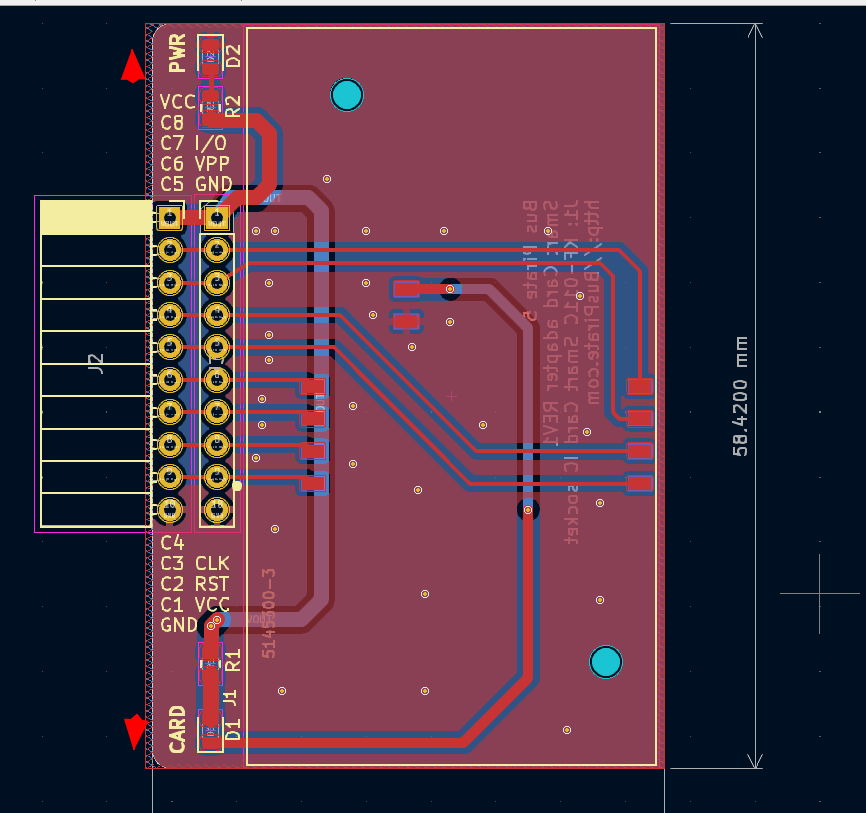
For those receiving boards, this is the LED orientation on REV2.
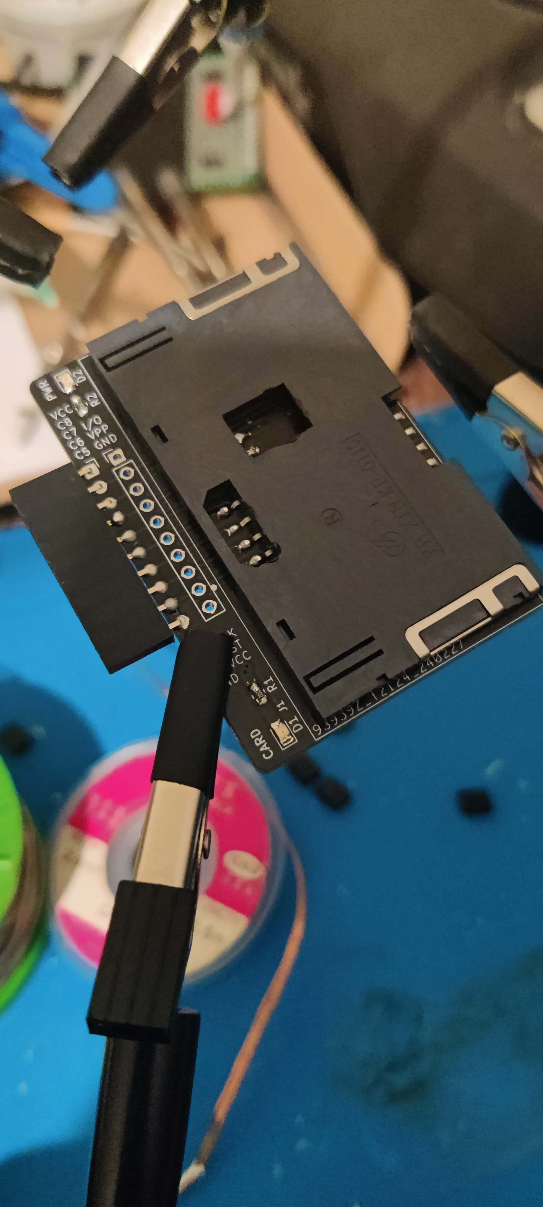
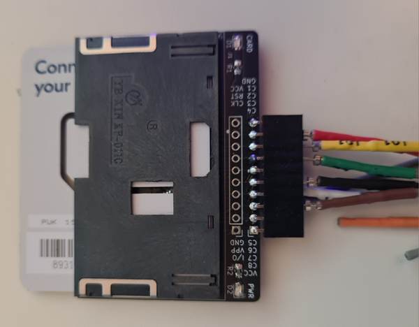
I’m using jumpers to connect to the data pins, and connecting the C6 and C1 directly to GND and VOUT on the Bus Pirate.
No cleaned up yet, but 2 wire mode is now getting the ATR reset response from the SLE4442 I sent with the PCBs.
I did it!
Looks good. But I still need to finish jumper wire on Q402 transistor to actually test that out
I added an SLE44xx ATR header fetch and decode. 0xa2131091 is the correct value, but there is something strange going on. My nice struct to wrap up the header didn’t work. I did it manually with >> &0bxx, but that also didn’t work. I tried to single step the code, but debug was all messed up. Gonna let this one ferment over night and finish up 2wire mode tomorrow.
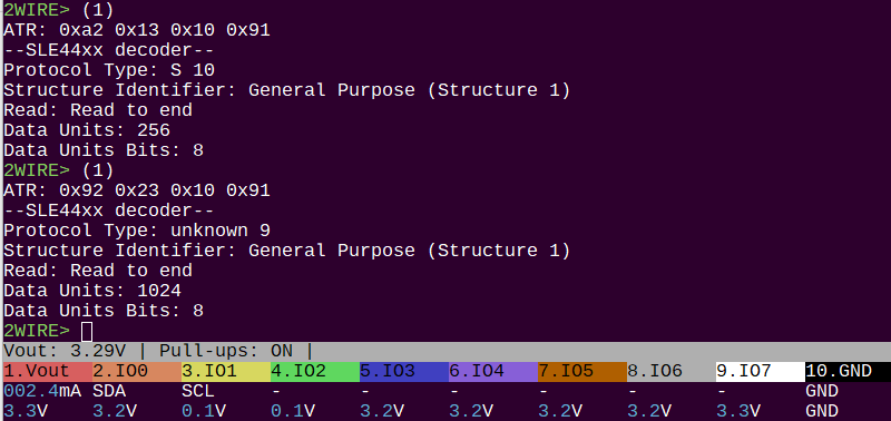
That’s what we want to see! SLE4442 and SLE4428 Smart Card ATR response.
I managed the LSB->MSB conversion using the Bus Pirate invert bits function, but I didn’t invert the bits in the datasheet… Took me way to long to figure out I was reading the datasheet backwards from the current bit order ![]()
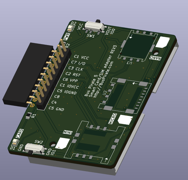
Here’s the final version with 3 SIM sockets and the smart card socket on the bottom. Modified IO pinout. Selector switches to choose VCC/GND from IO or normal power pins. This should be here soonish.
2Wire functions are now blocking, so they work as expected.
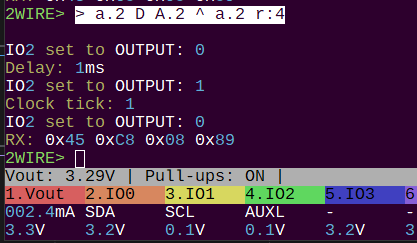
> a.2 D A.2 ^ a.2 r:4
If C2/RST pin is connected to IO2, this is a working syntax to get the card ATR info:
The LSB/MSB settings are not respected. I’ll fix that next.
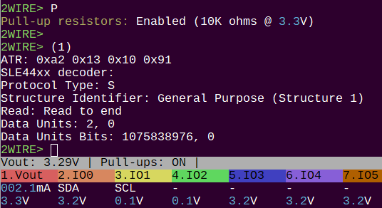
2WIRE> (1)
ATR: 0xa2 0x13 0x10 0x91
–SLE44xx decoder–
Protocol Type: S 10
Structure Identifier: General Purpose (Structure 1)
Read: Read to end
Data Units: 256
Data Units Bits: 8
2WIRE mode 20KHz, 3.3volts, pull-ups enabled. RST is connected to IO2. Macro (1) performs the ISO 7816-3 Answer To Reset (ATR) sequence and attempts to decode it.
2WIRE> L
Bitorder: LSB 0b00000001
These cards operate in the less-used Least Signification Bit (LSB) byte/word format. Enter L to set the Bus Pirate to LSB mode.
2WIRE> [0x30 0 0] r:256
I2C START
TX: 0x30
TX: 0 0
I2C STOP
RX: 0xA2 0x13 0x10 0x91 0xFF 0xFF 0x81 0x15
0xFF 0xFF 0xFF 0xFF 0xFF 0xFF 0xFF 0xFF
0xFF 0xFF 0xFF 0xFF 0xFF 0xD2 0x76 0x00
0x00 0x04 0x00 0xFF 0xFF 0xFF 0xFF 0xFF
0xFF 0xFF 0xFF 0xFF 0xFF 0xFF 0xFF 0xFF
Commands are signaled by an I2C like start and stop sequence. As we saw from the ATR, the card must be read all at once (256 bytes) before it accepts another command.
The ATR is repeated and then some data about the card. (what is it? don’t know yet)
2WIRE> [ 0x34 0 0] r:4
I2C START
TX: 0x34
TX: 0 0
I2C STOP
RX: 0xFF 0xFF 0xFF 0xFF
2WIRE>
0x34 reads protected memory
2WIRE> [ 0x31 0 0] r:4
I2C START
TX: 0x31
TX: 0 0
I2C STOP
RX: 0x07 0x00 0x00 0x00
2WIRE>
0x31 read security memory
2WIRE> = 0x07
=0x07 =7 =0b00000111
The first byte is the error counter. We have three tries left on this card.
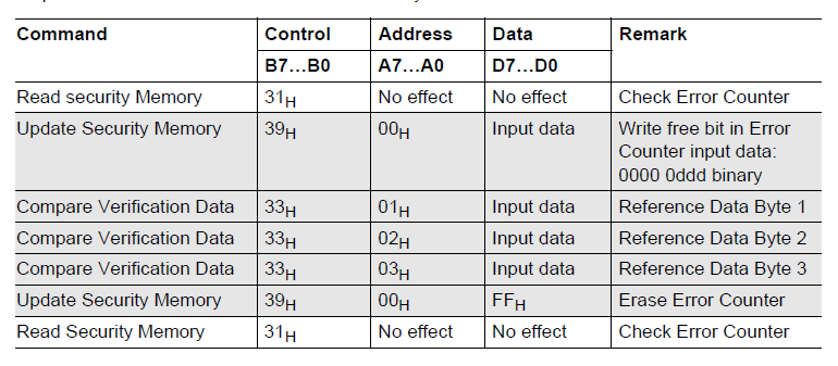
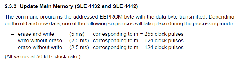
Processing commands need clock ticks. 255 or so, I did 500 to be safe. Most cards are default password 0xff 0xff 0xff. It seems like this sequence should be done on a single line - I did each step separately and burned out two protection bits before I got it unlocked.
2WIRE> [0x39 0 0]^:500 [0x33 1 0xff] ^:500 [0x33 2 0xff] ^:500 [0x33 3 0xff] ^:500 [0x39 0x00 0xff] ^:500 [0x31 0 0] r:4
I2C START
TX: 0x39
TX: 0 0
I2C STOP
Tick clock: 500
I2C START
TX: 0x33
TX: 1
TX: 0xFF
I2C STOP
Tick clock: 500
I2C START
TX: 0x33
TX: 2
TX: 0xFF
I2C STOP
Tick clock: 500
I2C START
TX: 0x33
TX: 3
TX: 0xFF
I2C STOP
Tick clock: 500
I2C START
TX: 0x39 0x00 0xFF
I2C STOP
Tick clock: 500
I2C START
TX: 0x31
TX: 0 0
I2C STOP
RX: 0x07 0xFF 0xFF 0xFF
2WIRE>
0x07 means we have 3 tries (0b111) left, meaning the attempt was successful and the card is unlocked and the tries counter reset.
I2C START
TX: 0x31
TX: 0 0
I2C STOP
RX: 0x00 0x00 0x00 0x00
2WIRE>
Evidently if you burn out 2 of 3 protection bits, unlock the card, reset the card, it says there are 3 tried left again. However, I deliberately did the wrong code and it burned out that last try. I think the fuse needs to be reset manually with a write. Will try that next, as well as changing the passcode… then a little utility to constantly burn fuses and reset, so we can look at the current consumption.
The OTHER thing that might be relevant at this point is the SLE4442 emulator. Perhaps one BP5 vs another? The license isn’t mentioned, so I contacted the project.
Great stuff is comming
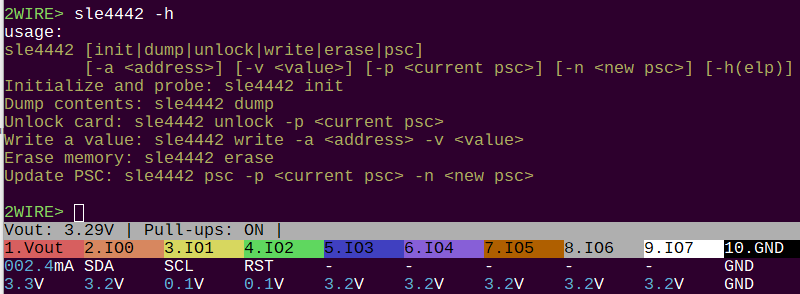
Mode specific commands (can I call them programs or apps?) are defo the way to go. I started one for SLE4442.
My immediate goal is to add some basic functionality, then write a loop that does wrong password-> pause for space->right password->reset counter. Then I’ll scope the Bus Pirate current sense resistor and see if the erase current is actually something we can capture.
Given the fact that we need to provide ~255 write clocks, my guess is we can slow down the clock and cont down to the tick that triggers the bit burn on a wrong attempt. However, I also bet we need PFETs on all the lines and a way to shut them down fast to stop the burn. Maybe even NFETs to ground to remove parasitic capacitance. It will be fun to see. I’m very excited.
I’d help you in the testing, but without a reader, we’re limited. I hope you make some available in the store soon.
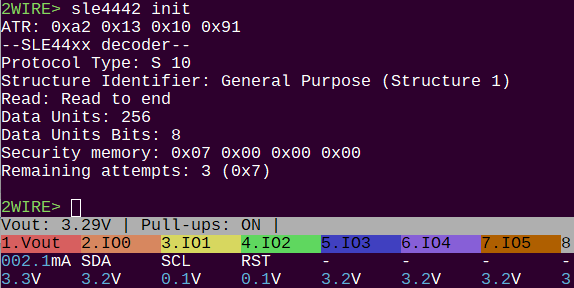
2WIRE> sle4442 unlock -p 0xffffff
–SLE44xx decoder–
ATR: 0xa2 0x13 0x10 0x91
Protocol Type: S 10
Structure Identifier: General Purpose (Structure 1)
Read: Read to end
Data Units: 256
Data Units Bits: 8
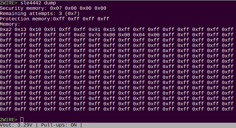
Security memory: 0x07 0x00 0x00 0x00
Remaining attempts: 3 (0x7)
Unlocking with password: 0xFFFFFF
Using free security bit: 3 (0x03)
Card unlocked, security bits reset
Macro (1) is removed. The sle4442 program takes it’s place. It seems to be reliable now. I only burned out two cards in the process, so success!
2WIRE> sle4442 psc -p 0xffffff -n 0x000000
–SLE44xx decoder–
ATR: 0xa2 0x13 0x10 0x91
Protocol Type: S 10
Structure Identifier: General Purpose (Structure 1)
Read: Read to end
Data Units: 256
Data Units Bits: 8
Security memory: 0x07 0x00 0x00 0x00
Remaining attempts: 3 (0x7)
Unlocking with PSC: 0xFFFFFF
Using free security bit: 0x03
Card unlocked, security bits reset
Security memory: 0x07 0xff 0xff 0xff
Remaining attempts: 3 (0x7)
Updating with PSC: 0x000000
PSC updated to: 0x000000
Security memory: 0x07 0x00 0x00 0x00
Remaining attempts: 3 (0x7)
Setting a new password with verification and emergency revert to 0xffffff.
For some reason I cannot get the protection bits to burn. I’m going to have one final go, and then just leave it out and push.
The final boards arrive to the office tomorrow. The plan is usually to ship them to me for assembly and testing. It is a pretty simple board though, I could have some made up and put in the shop. There is the risk of some issue though, I don’t know how receptive everyone is to that.
I gave up on the byte protection bits, but the rest is working ok. I’m going to push and move on to other cleanup.
Just looking into SIM cards, or Javacards (microcontroller cards running code compiled with a Java compiler).
The pickings are pretty slim, but I found this arduino sim card script (shout out to dangerous prototypes open logic sniffer by the author in the comments):
https://sourceforge.net/p/arduinosclib/code/HEAD/tree/trunk/SCLib.cpp#l524
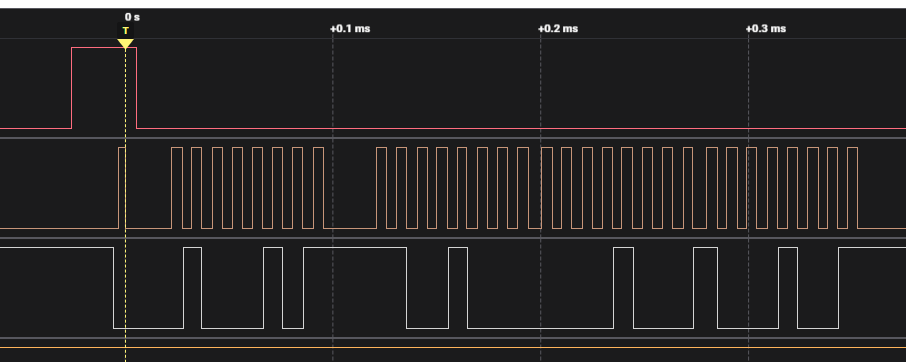
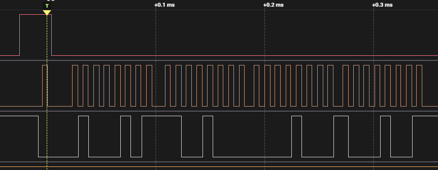
And this logic analyzer screenshot at hack a day:
It seems what happens:
This is significantly different than the sle4442. Bus pirate generates a continuous clock and the sim response is powered by that clock. At least that’s my initial reading. I’ll try to get an ATR response tomorrow.
Somehow my trusty logic analyzer stopped working this weekend. Running sigrok under WSL is a real pain, so I’m flying blind here.
such as a standard UART), it can be set to 8 bits, 1 even parity bit, 2 stop bits (sometime negotiable to 1, see TC1); during the ATR, the baud rate should be 1/372 of the clock frequency received by the card (corresponding to an ETU of 372 clock cycles)
Wikipedia has as good a description as any.
Setup
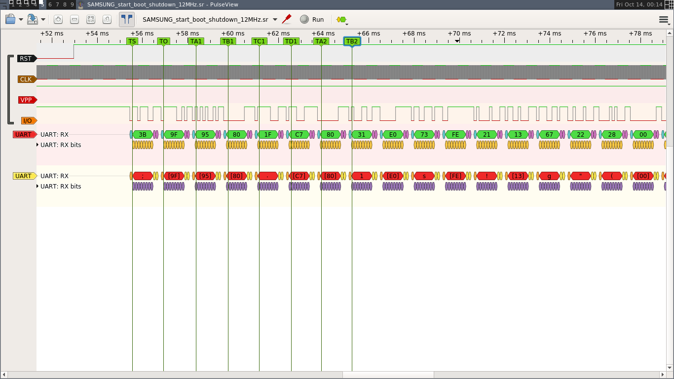
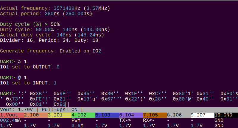
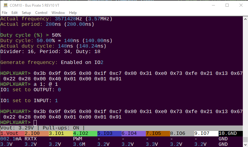
To perform the ATR just pull the SIM RST low (a 1), then release high (@ 1).
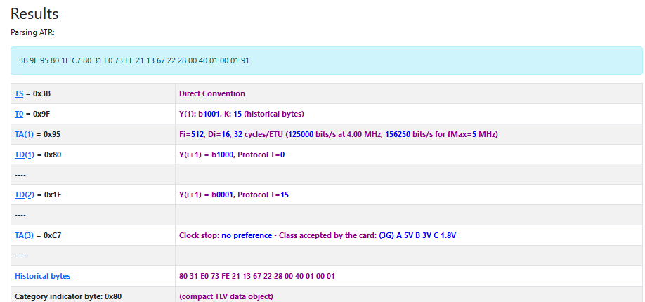
3B 9F 95 80 1F C7 80 31 E0 73 FE 21 13 67 22 28 00 40 01 00 01 91
Lycamobile Prepaid SIM-Card (Telecommunication)
http://lycamobile.at
And… it just worked like that! First try. This website has an ATR decoder and database.
It is in fact a LycaMobile SIM that I picked up for free at a grocery store in China Town.
Next steps:
Now I’m just plugging in random chip cards ![]() This is my Dutch debit card, which is not issued by anyone in the list.
This is my Dutch debit card, which is not issued by anyone in the list.
A university thesis with the most straight forward description of interfacing a SIM card that I’ve found.
First though, I need to make a half-duplex open drain UART in the PIO. Then we can try to read the contact list from the card (I know what it is because I used an app on my phone to look).
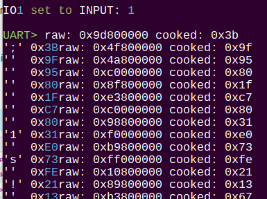
There’s half of our half-duplex UART in PIO. I’m using a Y splitter cable to connect the SIM card IO pin to both the normal UART RX pin and the half-duplex UART pin. The raw data includes the parity bit, which we could check for good measure, but that’s for later.
Making a generic UART that supports the different parity and stopbit combinations without hardcoding multiple programs is going to be a challenge. Also something for later.
I’ll get it added as a menu option and try to get TX going.