The PIO can be forced to execute commands. In this case I set the y register with the number of bits for a single TX/RX (data bits + parity bit + stop bit(s) - 2) action, then reload the x counter from that on each cycle. Easy!
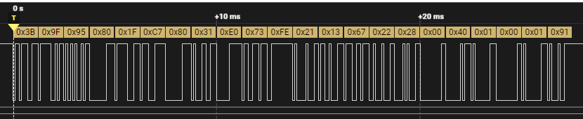
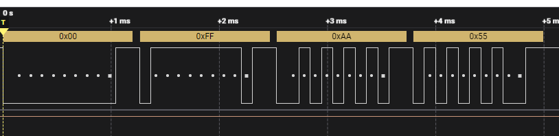
RX is working, now to hook up the logic analyzer and finish the transmit. Then tidy everything and we have a new mode feature complete vs the uart mode. Can’t believe it was this easy.
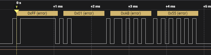
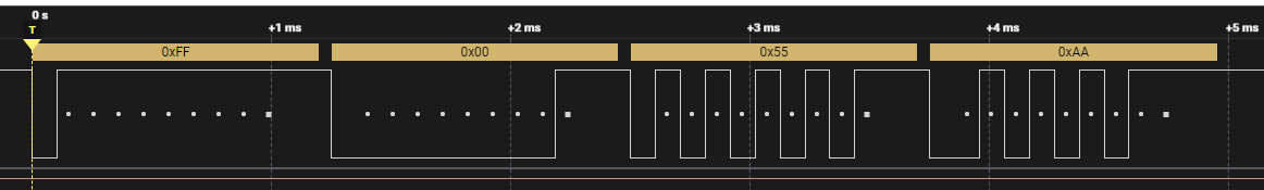
Transmit is 99% done, but output needs to be inverted.
gpio_set_oeover(pin_tx, GPIO_OVERRIDE_INVERT);
This works fine in the I2C PIO stuff, but when I use it here the output just disappears. It’s very strange, probably something obvious after I step away from it for a moment.
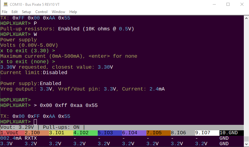
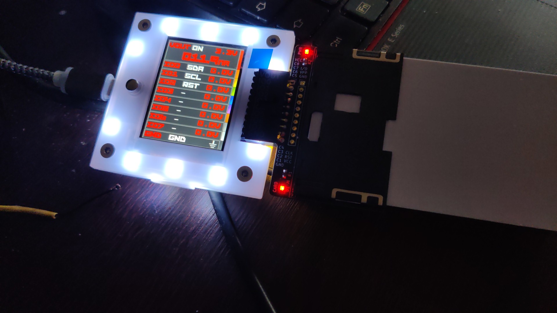
I just got replacement board. Flashed fresh FW and I get:
2WIRE> sle4442
Card not found
I tried many cards that I previously wrote because I thought that if there are all blanks then detection of ATR might not work but seems not the case.
Leds for power and card detection shine. I checked with continuity metter my solder work and seems fine. Is there some regression while cleaning up code?
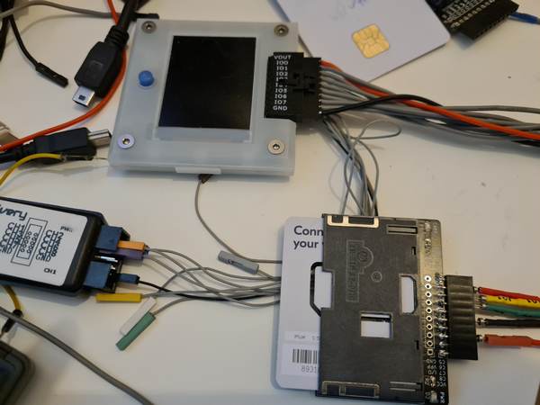
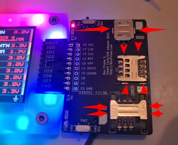
No its worse than that The pinout on that version of the adapter board doesn’t play well with the PIO, so I used jumper wires in development. I connected VCC/GND to VOUT/GND, and then IO/CLK/RST according to the labels on the displays.
I think I could actually make it work now that I understand the PIO side set arrangement better, but the next revision of the board has already been reconfigured
Do you have a few jumper wires? Or the probe cable?
This is how I’ve been debugging. Note that this is the wrong pin connection for the SLE4442, a pin is swapped for the clock I think (not on the cards, on my debug setup).
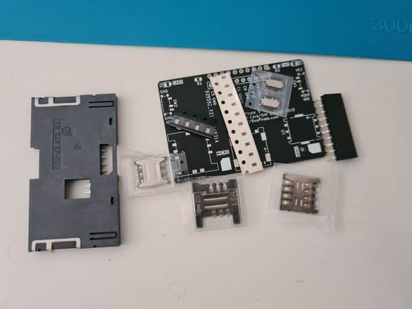
I can send the new board and connectors and stuff that arrived today. I think it is the final version, we’re getting production quotes. The only thing is the micro SIM socket is a real pain to solder, but do those really exist anymore?
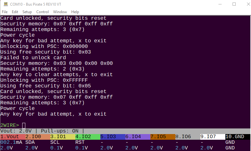
Wrote a loop to power cycle, pause, enter wrong password, pause, enter correct password and reset counter.
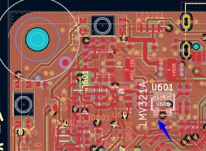
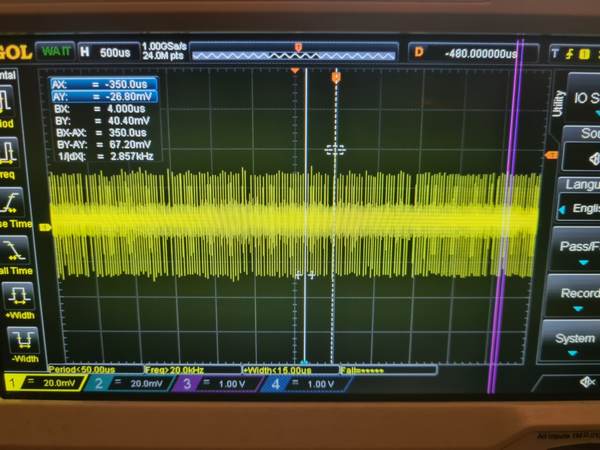
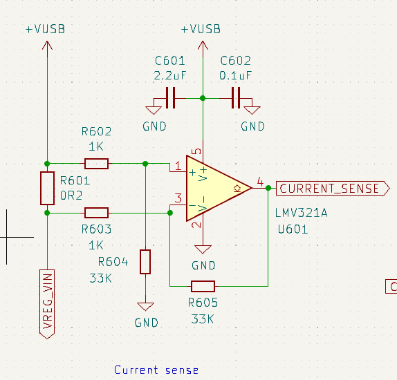
Measured the output of the current sense op-amp from pin 4 with my scope.
Alas, no repeatable triggering above the noise floor. This is probably because we’re measuring before about 10uF of capacitors, which are absorbing the big hit.
All is not lost. We can make an external version of the sense circuit and put between the card and all caps. The Bus Pirate iSense scales 0-500mA to a 0-3.3volt output, and uses a 0.2 ohm resistor.
Conveniently they don’t specify read/write/erase current in the datasheet. But, an isense that is 10ma or 12ma max will give a lot more resolution on small changes. A bigger voltage drop resistor would get rid of some noise because the op-amp gain will be a lot less.
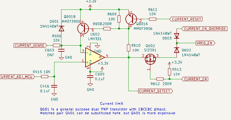
I’ve only ever seen this done with an FPGA, so maybe we can’t react fast enough with the RP2040. In that case, something like the current limit circuit controlling all IO pins and power through PFETs would be even faster than an FPGA and a lot cheaper.
I managed to solder Smardcard adapter and it works! Flashed new firmware to check it out. And I am missing dumping SLE4442 content to file. May I request that?