Is there a SPI isolator for the BUS Pirate 5?
1 Like
How do you mean?
Words words
I am designing a motherboard tester. Bus Pirate 5’s direct connection to the motherboard’s BIOS blocks PCH and CLK, so an SPI isolator is required.
1 Like
Is that something like this? That’s for optoisolation though it seems, not for sharing the bus.
I am unaware of any kind of device that allows simultaneous sharing of the SPI bus. Do you have a link to an example device?
Would an open drain style SPI output that is held high by pull-up resistors be useful? Then the Bus Pirate IO could idle high (weak pull-ups) and the BIOS would be free to “override” the pull-up. It would be a hit in speed though.
My idea was to connect the Bus Pirate 5 using SOP8 pliers to the BIOS of the motherboard of a laptop or PC and in this way determine which BIOS chip is, whether it is OK, compare it with the dump for that board, determine the existence of voltage (5V or 3.3V), CLK, PCH, … All this works OK if the board is without power (adapter or battery), but the board is blocked when it is under voltage and the Bus Pirate 5 is connected to the board in SPI mode. So I want to try the SPI isolator as in the diagram:
┌──────────────┐
│ BUS PIRATE │
│ 5 │
└──────┬───────┘
│ MOSI / CLK / CS
▼
┌────────────────────┐
│ SPI ISOLATION │ ◄── OE (HiZ / ACTIVE)
│ 74LVC125 (x3) │
└──────┬─────────────┘
│
▼
┌────────────────────┐
│ SOP8 BIOS CLIP │
│ (IN-CIRCUIT) │
└────────────────────┘
VCC LOGIC:
BIOS_VCC ─┐
├─► AUTO OR ► VCC_ISO (1.8 / 3.3)
BP5_VOUT ─┘
1 Like
If you just want the bus pirate out of the way you can disable power with w command or go to HiZ mode.
Yes, but I want to determine the state of the BIOS chip and the signals on it in order to detect a malfunction on the laptop board, and I can only do that from the SPI mode, which affects the signals on the motherboard (CLK, PCH/BUS…) and thus blocks the operation of the board…
1 Like
I understand your drawing. Would a command to make the buffers high impedance and input work?
Maybe. It’s worth a try.
Would this be something that using bp6 in follow along analyser would be useful. Let the logic analyser decode spi
1 Like
I added a (temporary) command to the SPI mode in this firmware:
bus_pirate5_rev10-SPI-ISO.zip (394.2 KB)
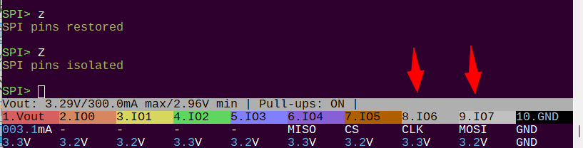
Zdisengages the SPI pins from the GPIO pad, makes the pin and buffer inputs. You can see here that the CLK and MOSI pins float high when isolated.zdisables isolation and returns the pins to the original state.
Please let me know if this is what you had in mind. If this works for your use, I’ll add it into the main source and update documentation.
I am testing ‘Z’ and ‘z’ in SPI mode. I haven’t fully completed the tests but I noticed that ‘w’ doesn’t work because VOUT is OFF but it shows the voltage (3.3V if W 3.3 is used)
1 Like
Thank you so much for the test! I’m sorry, I’m also doing a revamp on the power supply driver and I’ll investigate this issue immediately.
~(self test) → VOUT ERR
1 Like
Where does it show 3.3V while VOUT is off?
The LCD shows the actual measured voltage, the bottom line of the toolbar shows live measurement. The only place it should say 3.3V if there is no voltage is in the top line of the toolbar.
Also, if you start the supply with W and the voltage does not reach the intended target, the power supply should report an error and disable itself. If voltage drops too much (10%) in the latest firmware you will also get an alarm and an error.
In general it should not be possible to enable the power supply if it does not output a voltage. However, I did a huge update this weekend and there are bound to be errors. I will debug this further if you can provide some additional information.
bus_pirate5_rev10.zip (393.3 KB)
Here is a firmware with the z/Z command in SPI mode based on the old PSU driver.
After testing Z and z and exiting SPI mode, VOUT OFF 3.3V remains on the BP5 screen. So I did a test(~) and got BP5 VOUT ERR on the display. I will now test the new version and report my impressions.
1 Like
Thank you so much for the added details. I found the bug (PSU disable not working) and pushed a fix.
What are the commands for individual setting of parameters in SPI mode (s for speed…)
There are none. Adding long flags for parameters is an ongoing discussion.