Firmware main branch @ bbf76e0 (Jan 31 2025 15:45:37)
RP2040 with 264KB RAM, 128Mbit FLASH
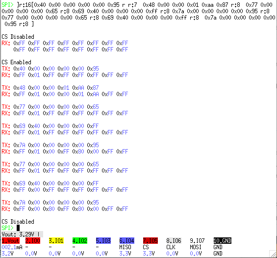
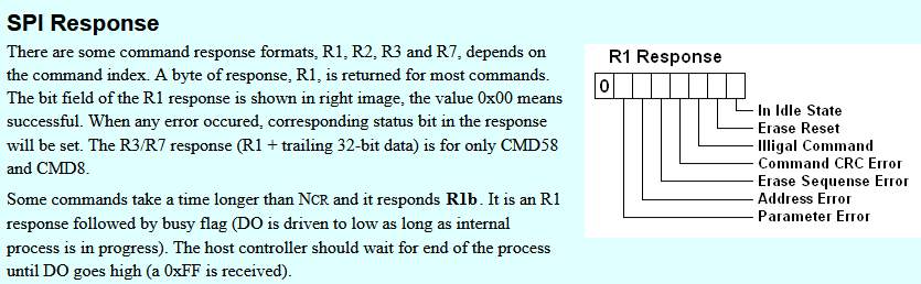
I’m trying to work my way through the startup sequence for an SD card using SPI. It’s working admirably well, but I’m curious about the output of the BP commands: they seem to have an extra 0xFF byte before the expected data. Eg: 0xFF 0x01. Is that normal? So, for a command that’s supposed to return Format R1, of 8 bits, is it supposed to be 16 bits, instead? How do I interpret this output, even though it otherwise looks correct? In my microcontroller, I can easily read an extra byte before the “real” data, but am I misunderstanding something?
Can you describe what you are attempting to do and what the expected response would be?
I looked through the SD card command set and I don’t see anything as high as 0x40, 0x48, 0x77, 0x69, etc. The common commands are CMD0-CMD25ish. I also strongly suspect that CS should go high/low between each bus transaction, but do not know for sure.
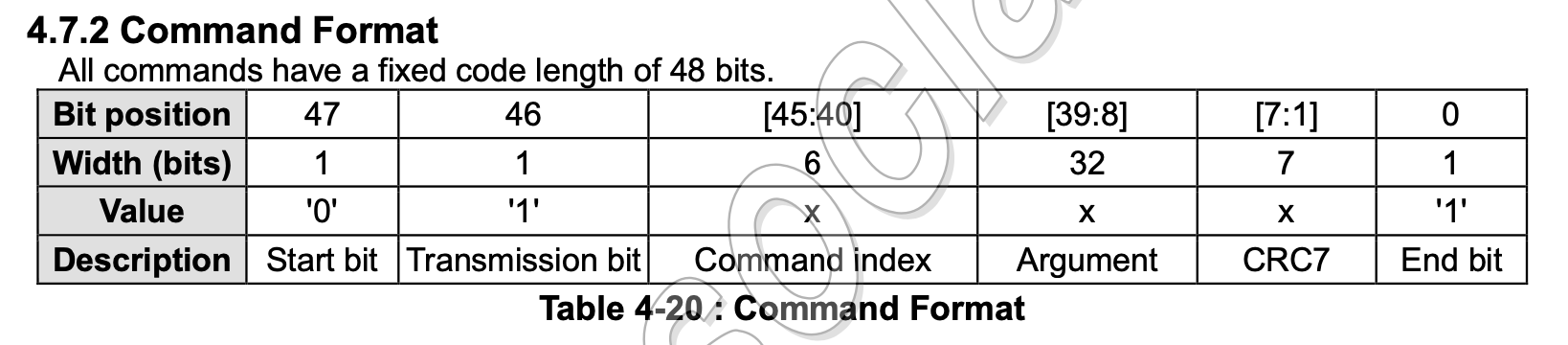
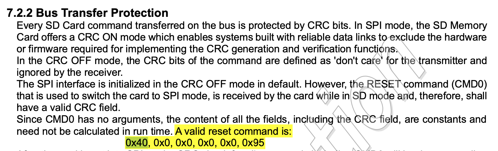
Thanks, Ian - I have the same doc open. The commands are or’d with 0x40, so command 0x00 would actually be 0x40, etc.
I’ve verified that the startup sequence actually works with a couple of different cards, so I’m going to wire it up to the µcontroller, and do some debugging, there, to see if that first 0xff output byte actually exists in the stream. I’ll post back after, just for completeness.
I spent all day on the µcontroller, and I’m seeing some fundamental issues - which aren’t your problem, but I’d appreciate some insight, nonetheless.
In the image I shared, above, MISO is at 3.3v idle, while MOSI is 0v. Is that “normal”? I mean, the SD card works, but it’s different from what I see on the scope from my µcontroller, a FRDM-KL25Z. On the KL25Z, it looks like both lines ride at 3.3v idle. On a different project that I can verify works, using a Sony Spresense, the SPI lines are like the BP’s: MISO idles high, and MOSI idles low. So it looks like those line levels are “normal.”
I’d appreciate some insight on this aspect from someone who knows more than me.
MISO idle depends on the card, and unless you have the Bus Pirate pull-ups enabled I believe it is actually the card outputting high or has a pull-up of its own.
MOSI idle, I believe, is chip dependent. That would be in the RP2040 datasheet. We also have a 1M Ohm pull-down on all pins.
If the resting state of a pin is an issue, another post reminded me that 3Wire mode is the same as API but with granular control of individual pins with _-/\·! Syntax commands.
I did, in fact, finally get it to work. It’s basically the equivalent of “r:8” after each command. In the µcontroller - at least with the KL25, and I suspect with the new MCXC444, which has the same SPI register layout - I needed to “tickle the clock” for a few bytes after each command, so the slave device could send the data back. No clock, no response data. I didn’t know it was a requirement of the protocol, though it makes sense, after reading it.
In my KL25 app, I just ignore 0xff bytes until the first non-0xff byte. In BP, I can live with a few stray bytes. But, yeah, it appears to be “normal” to get 0xffs like I showed in my first image.
[OT]
@ evil-aaronm
Hi, evil-aaronm.
I apologize for my OT, but the behavior you describe is the same as that shown by Bus Pirate V3.6, so I believe that nothing is wrong there.