Is there a SPI sniffer feature yet?
Can I increase the terminal baudrate to capture more traffic? Or even sniff to flash?
2 Likes
Not yet, but I think I can make something with the PIO that would sniff up to 62.5 (or maybe half that).
I have an application where I have 4MHz SPI clock, so that should be more than sufficient
1 Like
It’s on my list. I love the PIO and am getting better at it. I’ll try to make something demo-able tomorrow.
Very cool, thanks. Would be very useful for debugging for me.
It’s starting to work. There’s some weirdness about the startup state of the CS pin when the sniffer engages. I’m looking into that.
So, there’s always a catch with the PIO and there’s a decision to be made.
PIO input pins are consecutive. The clock has to come after the data pins.
- DATA0
- DATA1
- CLOCK
- CS
It can’t match the order of the hardware SPI pins, so I added it to the top four IO pins.
There’s two way to get both data lines. First is two separate PIO programs handling one data pin each. The other is a single program that grabs both data pins and we sort other the every-other-bit data in software. I’m leaning towards the second because we can stream to RAM with a single DMA setup, instead of two.

Better. I’m going to push this as a kind of preview, but don’t expect much yet.
Somewhere someone mentioned we could probably get around clock/6 for speed. 125/6=~20MHz. It works reliably for me at 15.6MHz, but at 30MHz it starts loosing bits. That’s probably as fast as we get without overclocking the pico to 200mhz.
1 Like
Gee, that was fast. Excellent service, thanks. I will be back in the lab on Monday, do you think I could have a build for testing by then?
So how can I keep up with the data coming in? Can I crank up UART speed? Or is there a way to write to flash?
This is just a tiny proof of concept because it sounded like a fun project.
There’s currently no way determine CS change from the data coming from the PIO, that’s going to take some thought.
UART speed has no effect on USB CDC generally speaking.
Logging to flash is easy, but what format should it be? If binary, is it a 8bits+8bits+csbits long format? If in clear text, can we keep up while doing the ASCII conversions?
For now I’m going to try to get full duplex going and maybe see if there’s an easy way to track cs changes
1 Like
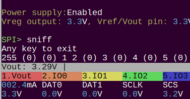
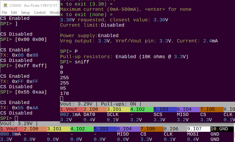
There’s a new build with full duplex sniffing. It’s using two PIO programs, one for each data pin. You can see from the (0) before the 1 2 that now it’s needed to determine which byte pairs go together. Perhaps the single program with intermingled bits is a better approach.
; This program is a simple SPI sniffer that captures the data on the SPI bus
; inspired by https://github.com/raspberrypi/pico-examples/issues/104
; data must be first pin, clock n pins after

no_data:
    mov isr, null       ; bad data, empty ISR
    jmp is_cs_low       ; check if CS is low
public entry_point:
.wrap_target
data_in:
    wait 0 pin 2        ; wait for clock to go low
    wait 1 pin 2        ; wait for clock to go high
    in pins, 1          ; sample data WE CAN CHANGE THIS TO 2 TO INTERLEAVE BITS
is_cs_low:
    jmp pin, no_data    ; if CS is high, ignore data
.wrap
The PIO program is really slick. It always samples bits, but if CS is high we just flush the buffer on every cycle. Changing in pins, 1 to in pins, 2 would allow a single program to handle both data pins, but the bits will be interleaved.
At the moment I don’t see any obvious way to flag that the CS pin changed. If the bits are interleaved we can use a 16bit shift register size to get both bytes. maybe add an extra bit to signal the first byte in a new frame. But we probably need to mark first and last byte, which is going to eat into our max speed.
Anyone have thoughts on this? It’s an interesting problem. I’ll ponder it over and pick it back up in a few days.
1 Like
Very nice, thanks. I will report my results.
The problem with marking CS is that you have no symbols reserved for anything except data. For the single-pin version, you’re logging a single bit, so 0 == low and 1 == high. There is no other value.
For the two-pin version, the same basic problem.
You need to log more than two bits per cycle, and then do some post-processing to only extract the data bits.
What do you think about the following PIO program, which logs four bits per cycle?
start:
cs_program_exit:
    ; Ensure final 2k of data is output via the ISR
    ; Since each loop writes 4 bytes, this requires 0x1FF writes.
    ; Since the JMP check is done pre-decrement, start at 0x1FE.
    set Y, 0x1FF ; Need to write 0x1FF times, jmp checks pre-decrement
cs_fill_2k
    set X, 0xFFFFFFFF
    in X, 32
    jmp Y-- cs_fill_2k ; Ensure final 2k DMA trigger
    ; Then drop into the infinite loop, ready to start another trace

infinite_loop:
    jmp infinite_loop

cs_changed_to_high:
    set X, 0xFFFFFFF3 ; logged when CS changed to high
    in X, 32 ; 0b0001 is CS low->high

cs_stayed_high:
    ; set pins, LED_OFF ; indicate tracing stopped
    jmp pin, cs_stayed_high ; while CS stays high, do nothing more

cs_changed_to_low:
    ; set pins, LED_ON ; indicate tracing occuring
    set X, 0xFFFFFFF2 ; ensure flushed buffer!
    in X, 32  ; 0b0010 is CS high->low

.wrap_target
data_in:
    wait 0 pin 2  ; wait for clock to go low
    wait 1 pin 2  ; wait for clock to go high
    in pins, 2       ; two data bits logged
    in null, 2        ; and two zero bits logged
is_cs_low:
    jmp pin, cs_changed_to_high
.wrap
The main data logging takes minimum of five clock cycles instead of four cycles, because of the need to pad with two zero bits.
Technically, you could do this with logging only three bits per cycle, since there are only six symbols to be encoded. However, this will still take five clock cycles, the logic would be much more involved, and I’d have to think about how to encode / find CS transitions at arbitrary bit position in a binary stream.
In contrast, as conceptualized, each nybble can be independently analyzed:
| Value | Meaning |
|---|---|
0bAB00 |
Logged Data: Data0 is A, Data1 is B |
0b1111 |
Filler … used to ensure ISR is flushed |
0b0010 |
CS high->low |
0b0001 |
CS low → high |
other |
Unused / invalid |
To start tracing, use pio_sm_exec() to jump to cs_stayed_high.
To stop tracing, use pio_sm_exec() to jump to cs_program_exit. This ensures a final 2k of filler data is DMA’d, ensuring the last samples get logged to the file (without writing any additional code to handle this edge condition).
Hook up the ISR to a DMA engine, filling 2k pages of data (two, in a ring buffer). Each time a page is filled, write that 2k block of data to the flash memory.
Note: This is entirely conceptual … haven’t even seen if the above compiles.
1 Like
@ian - would like your thoughts on the above SPI sniffer code.
I tried to resolve your question of how to log the CS transitions, with sample PIO program.
2 Likes
Brilliant as always. This solves the issue of CS well. The DMA part I can’t comment on until reading a bit more.
I flagged this thread and added this to my to-do list. I will probably try it without the DMA first, but there is a “BIG_BUFFER” shared for DMA stuff that an be used.
1 Like
Thanks. Because this is all conceptual, please note that the bit order may be off. For example, you might need to swap the order of the following two lines:
    in pins, 2       ; two data bits logged
    in null, 2        ; and two zero bits logged
And adjust the decoder, which might look like:
| Value | Meaning |
|---|---|
0b00BA |
Logged Data: Data0 is A, Data1 is B |
0b1111 |
Filler … used to ensure ISR is flushed |
0b0100 |
CS high->low |
0b1000 |
CS low → high |
other |
Unused / invalid |
Again… the code is conceptual in nature, and still needs validation for the bit ordering and the like. Might not work at all … but hope it gives you ideas to move forward with! ![]()
1 Like
8 months later and I’m back to this one ![]()
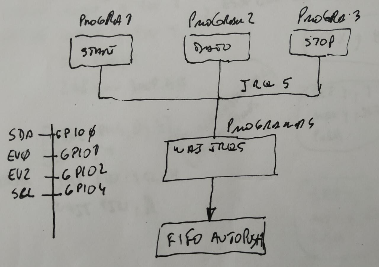
The [I2C sniffer] I implemented today uses 4 state machines and 2 IO pins. I feel like there’s some extra inspiration there as well. Maybe two SMs can be coordinated through IRQ or a GPIO pin.
It also uses a MOV and IN pins to capture the state of the data line for ACK/NAK, which is something I think could be useful for capturing CS in the upper bits 9-15.
3 Likes
hi everyone! is this feature supported yet? also, can i run this code on a standard pico? i was able to get the i2c sniffer running on my pico but i can’t find anything for the SPI sniffer.
2 Likes
Sorry misunderstood. SPI sniffer is yet to be implemented.
1 Like