Hey gang, sorry I’ve been away for a while…
I used this color sensor in a production project about 8 years ago  I don’t know if this is useful, but here’s some of my code for reference. It worked quite well and I was able to detect the color objects passing by the sensor at a pretty decent rate. It was a pretty integral part of the machine.
Yeah, I remember the datasheet for this being a real mess, and I spent more time that I should have getting it all to work.
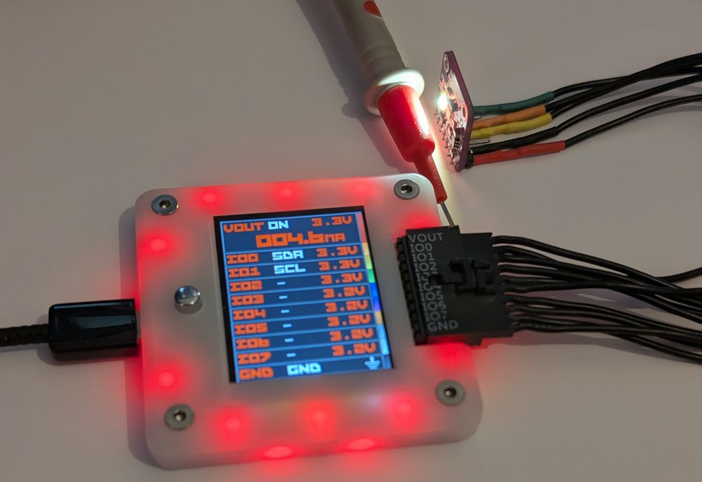
The device doing the control was an ATMega328u4, basic 8-bit AVR, with USB. Basicallly, the sensor was on the side of a piece of transparent PVC tubing watching colored balls fall through (accelerated by gravity). The supervisory process would talk over a serial protocol, looking for a certain colored ball in an array of other colored balls.
header/defines
/******************************************************
* tcs34725
*******************************************************
* defines and methods for the TAOS TCS34725 color
* sensor chip
******************************************************/
#ifndef TCS_34725_H_
#define TCS_34725_H_
/**************************************
* SPI Defines for the chip
**************************************/
// correct chip ID
#define TCS34725_CHIP_ID (0x44)
// SPI address of chip
#define TCS34725_ADDRESS (0x29)
// commands
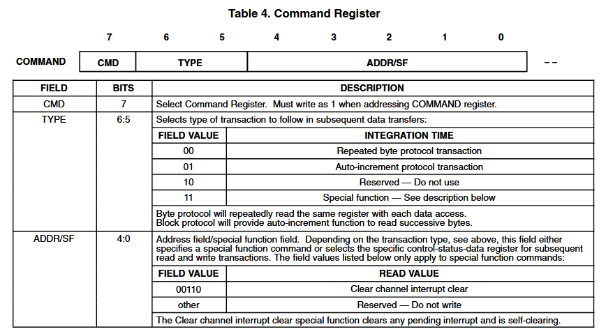
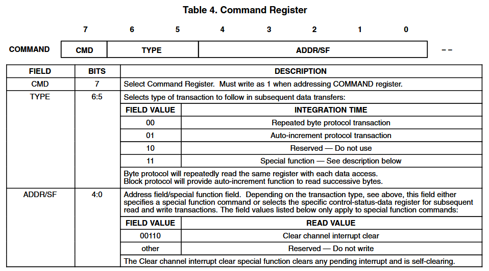
#define TCS34725_COMMAND_BIT (0x80) // bit must be set for any command
#define TCS34725_CMD_REPEATED_BYTE (TCS34725_COMMAND_BIT) // read the same byte over and over and over
#define TCS34725_CMD_AUTO_INC (TCS34725_COMMAND_BIT | 0x20) // after read, read the next byte
#define TCS34725_CMD_SPECIAL (TCS34725_COMMAND_BIT | 0x60) // do something special (only special is next one)
#define TCS34725_CMD_ADDR_CLR_INT (TCS34725_COMMAND_BIT | 0x06) // clear any pending interrupts
// Register addresses
#define TCS34725_ENABLE (0x00)
#define TCS34725_ATIME (0x01) // Integration time
#define TCS34725_WTIME (0x03) // Wait time (if TCS34725_ENABLE_WEN is asserted)
#define TCS34725_AILTL (0x04) // Clear channel lower interrupt threshold
#define TCS34725_AILTH (0x05)
#define TCS34725_AIHTL (0x06) // Clear channel upper interrupt threshold
#define TCS34725_AIHTH (0x07)
#define TCS34725_PERS (0x0C) // Persistence register - basic SW filtering mechanism for interrupts
#define TCS34725_CONFIG (0x0D)
#define TCS34725_CONTROL (0x0F) // Set the gain level for the sensor
#define TCS34725_ID (0x12) // 0x44 = TCS34721/TCS34725, 0x4D = TCS34723/TCS34727
#define TCS34725_STATUS (0x13)
#define TCS34725_CDATAL (0x14) // Clear channel data
#define TCS34725_CDATAH (0x15)
#define TCS34725_RDATAL (0x16) // Red channel data
#define TCS34725_RDATAH (0x17)
#define TCS34725_GDATAL (0x18) // Green channel data
#define TCS34725_GDATAH (0x19)
#define TCS34725_BDATAL (0x1A) // Blue channel data
#define TCS34725_BDATAH (0x1B)
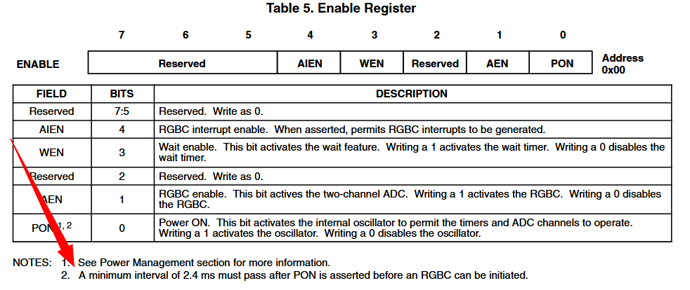
// enable modes/commands for the enable register
typedef enum {
TCS34725_ENABLE_AIEN = 0x10, // RGBC Interrupt Enable
TCS34725_ENABLE_WEN = 0x08, // Wait enable - Writing 1 activates the wait timer
TCS34725_ENABLE_AEN = 0x02, // RGBC Enable - Writing 1 actives the ADC, 0 disables it
TCS34725_ENABLE_PON = 0x01 // Power on - Writing 1 activates the internal oscillator, 0 disables it
} tcs34725_enable_t;
// wait times for the wait time register
typedef enum {
TCS34725_WTIME_2_4MS = 0xFF, // WLONG0 = 2.4ms WLONG1 = 0.029s
TCS34725_WTIME_204MS = 0xAB, // WLONG0 = 204ms WLONG1 = 2.45s
TCS34725_WTIME_614MS = 0x00 // WLONG0 = 614ms WLONG1 = 7.4s
} tcs34725_wait_t;
// persistence values
typedef enum {
TCS34725_PERS_NONE = 0x00, // Every RGBC cycle generates an interrupt
TCS34725_PERS_1_CYCLE = 0x01, // 1 clean channel value outside threshold range generates an interrupt
TCS34725_PERS_2_CYCLE = 0x02, // 2 clean channel values outside threshold range generates an interrupt
TCS34725_PERS_3_CYCLE = 0x03, // 3 clean channel values outside threshold range generates an interrupt
TCS34725_PERS_5_CYCLE = 0x04, // 5 clean channel values outside threshold range generates an interrupt
TCS34725_PERS_10_CYCLE = 0x05, // 10 clean channel values outside threshold range generates an interrupt
TCS34725_PERS_15_CYCLE = 0x06, // 15 clean channel values outside threshold range generates an interrupt
TCS34725_PERS_20_CYCLE = 0x07, // 20 clean channel values outside threshold range generates an interrupt
TCS34725_PERS_25_CYCLE = 0x08, // 25 clean channel values outside threshold range generates an interrupt
TCS34725_PERS_30_CYCLE = 0x09, // 30 clean channel values outside threshold range generates an interrupt
TCS34725_PERS_35_CYCLE = 0x0a, // 35 clean channel values outside threshold range generates an interrupt
TCS34725_PERS_40_CYCLE = 0x0b, // 40 clean channel values outside threshold range generates an interrupt
TCS34725_PERS_45_CYCLE = 0x0c, // 45 clean channel values outside threshold range generates an interrupt
TCS34725_PERS_50_CYCLE = 0x0d, // 50 clean channel values outside threshold range generates an interrupt
TCS34725_PERS_55_CYCLE = 0x0e, // 55 clean channel values outside threshold range generates an interrupt
TCS34725_PERS_60_CYCLE = 0x0f // 60 clean channel values outside threshold range generates an interrupt
} tcs34725_persistence_t;
// config for long wait times
#define TCS34725_CONFIG_WLONG (0x02) // Choose between short and long (12x) wait times via TCS34725_WTIME
// status values
#define TCS34725_STATUS_AINT (0x10) // RGBC Clean channel interrupt
#define TCS34725_STATUS_AVALID (0x01) // Indicates that the RGBC channels have completed an integration cycle
typedef enum {
TCS34725_INTEGRATIONTIME_2_4MS = 0xFF, // 2.4ms - 1 cycle - Max Count: 1024
TCS34725_INTEGRATIONTIME_4_8MS = 0xFE, // 4.8ms - 2 cycles - Max Count: 2048
TCS34725_INTEGRATIONTIME_9_6MS = 0xFC, // 9.6ms - 4 cycles - Max Count: 4096
TCS34725_INTEGRATIONTIME_24MS = 0xF6, // 24ms - 10 cycles - Max Count: 10240
TCS34725_INTEGRATIONTIME_50MS = 0xEB, // 50ms - 20 cycles - Max Count: 20480
TCS34725_INTEGRATIONTIME_101MS = 0xD5, // 101ms - 42 cycles - Max Count: 43008
TCS34725_INTEGRATIONTIME_154MS = 0xC0, // 154ms - 64 cycles - Max Count: 65535
TCS34725_INTEGRATIONTIME_700MS = 0x00 // 700ms - 256 cycles - Max Count: 65535
} tcs34725_integration_time_t;
typedef enum {
TCS34725_GAIN_1X = 0x00, // No gain
TCS34725_GAIN_4X = 0x01, // 4x gain
TCS34725_GAIN_16X = 0x02, // 16x gain
TCS34725_GAIN_60X = 0x03 // 60x gain
} tcs34725_gain_t;
bool initTCS(tcs34725_integration_time_t intTime, tcs34725_gain_t gain);
bool tcsWrite8(unsigned char addr, uint8_t val);
uint8_t tcsRead8(unsigned char addr);
uint16_t tcsRead16(unsigned char addr);
bool getAllColors(color_array_t* colors);
void tcsWriteIntegrationTime(tcs34725_integration_time_t intTime);
void tcsWriteReceiveGain(tcs34725_gain_t gain);
#endif
tcs334725.c
/******************************************************
* tcs34725
*******************************************************
* methods for the TAOS TCS34725 color sensor chip
*******************************************************/

#include "tcs34725.h"

/**************************************
* get the chip up and running
**************************************/
bool initTCS(tcs34725_integration_time_t intTime, tcs34725_gain_t gain) {
    initTWI();

    tcsWriteIntegrationTime(intTime);
    tcsWriteReceiveGain(gain);

    // chip is in low power sleep mode when first powered up.  Tell
    // it to wake the heck up.
    return (tcsWrite8(TCS34725_ENABLE, TCS34725_ENABLE_PON | TCS34725_ENABLE_AEN));
}

/*********************************************
* write a single byte
*********************************************/
bool tcsWrite8(unsigned char addr, uint8_t val) {
    return (twiWriteSingleByte(addr, val, false));
}

/***********************************************
* read a single byte
***********************************************/
uint8_t tcsRead8(unsigned char addr) {
    uint16_t retVal = twiReadSingleWord(addr);

    return ((uint8_t)(retVal >> 8));
}

uint16_t tcsRead16(unsigned char addr) {
    return (twiReadSingleWord(addr));
}

/*******************************************
* integration time
*******************************************/
void tcsWriteIntegrationTime(tcs34725_integration_time_t intTime)
{
    tcsWrite8(TCS34725_ATIME, (unsigned char)intTime);
}

/*******************************************
* set receiver gain.  Gain is the lower
* 2 bits of the control register
********************************************/
void tcsWriteReceiveGain(tcs34725_gain_t gain)
{
    tcsWrite8(TCS34725_CONTROL, (unsigned char)gain);
}

bool getAllColors(color_array_t* colors) {
    if (twiReadMultipleWords(TCS34725_RDATAL, &colors->red, 3))
    {
        return (true);
    }

    return (false);
}
twi.h
/***************************************************
* TWI (I2C) Interface
***************************************************/

#ifndef TWI_H_
#define TWI_H_

void initTWI();
bool twiWriteSingleByte(unsigned char addr, unsigned char data, bool chain);
uint16_t twiReadSingleWord(unsigned char reg);
bool twiReadMultipleWords(unsigned char startReg, uint16_t* data, size_t len);

#endif // define TWI_H_
twi.c
/***************************************************
* TWI (I2C) Interface
***************************************************/

#include "project.h"
#include <util/twi.h>

/***********************************
* initTWI()
************************************
* Set the data and clock pins as
* outputs and set them both high
***********************************/
void initTWI() {
    TWSR = 0;   // prescaler of one
    TWBR = 32;  // should make TWI freq 200KHz
    //TWBR = 12;  // 400KHz
}

/*******************************************
* write a single byte
********************************************
* set 'chain' bool parameter to true if you
* are going to chain another operation after
* this (essentially, don't send a STOP)
********************************************/
bool twiWriteSingleByte(unsigned char addr, unsigned char data, bool chain) {
    // Send the start
    TWCR = BIT(TWINT) | BIT(TWSTA) | BIT(TWEN);

    // wait for it
    while (!GETBIT(TWCR, TWINT));

    // OK?
    if (TW_STATUS != TW_START)
    {
#ifdef SENSOR_STDIO
        printf_P(PSTR("TWI-W::Start not sent properly, TWSR is 0x%02x\r\n"), TW_STATUS);
#endif
        TWCR = 0;
        return (false);
    }

    // SLA+W
    unsigned char SLA = TCS34725_ADDRESS;
    // seven bit address, shift left one
    SLA = SLA << 1;
    // clear LSB to indicate a write
    SLA &= 0xfe;
    TWDR = SLA | TW_WRITE;
    TWCR = BIT(TWINT) | BIT(TWEN);

    // wait
    while (!GETBIT(TWCR, TWINT));

    if (TW_STATUS != TW_MT_SLA_ACK)
    {
#ifdef SENSOR_STDIO
        printf_P(PSTR("TWI-W::SLA+W not sent properly, TWSR is 0x%02x\r\n"), TW_STATUS);
#endif
        TWCR = 0;
        return (false);
    }

    // send command code.  This is the logic or of the command and register address
    unsigned char commandCode = TCS34725_CMD_REPEATED_BYTE | addr;
    TWDR = commandCode;
    TWCR = BIT(TWINT) | BIT(TWEN);

    // wait
    while (!GETBIT(TWCR, TWINT));

    if (TW_STATUS != TW_MT_DATA_ACK)
    {
#ifdef SENSOR_STDIO
        printf_P(PSTR("TWI-W::command code not sent properly, TWSR is 0x%02x\r\n"), TW_STATUS);
#endif
        TWCR = 0;
        return (false);
    }

    if (!chain)
    {
        TWDR = data;
        TWCR = BIT(TWINT) | BIT(TWEN);

        // wait
        while (!GETBIT(TWCR, TWINT));

        if (TW_STATUS != TW_MT_DATA_ACK)
        {
#ifdef SENSOR_STDIO
            printf_P(PSTR("TWI-W::data byte not sent properly, TWSR is 0x%02x\r\n"), TW_STATUS);
#endif
            TWCR = 0;
            return (false);
        }

        // send the stop
        TWCR = BIT(TWSTO) | BIT(TWINT) | BIT(TWEN);

        // wait for TWI stop condition
        while (!IS_SCL_HIGH && !IS_SDA_HIGH);

        TWCR = 0;
    }

    return (true);
}

/********************************************
* read a single byte
********************************************/
uint16_t twiReadSingleWord(unsigned char reg) {
    uint16_t retVal;

    if (twiReadMultipleWords(reg, &retVal, 1))
    {
        return (retVal);
    }

    return (0);
}

bool twiReadMultipleWords(unsigned char startReg, uint16_t* data, size_t len) {
    if (twiWriteSingleByte(startReg, 0, true))
    {
        // send the repeated start to chain the write with a read
        TWCR = BIT(TWSTA) | BIT(TWINT) | BIT(TWEN);

        // wait for it
        while (!GETBIT(TWCR, TWINT));

        // resend the SLA+R, but with the lowest bit set to indicate a read
        unsigned char SLA = TCS34725_ADDRESS;
        // seven bit address, shift left one
        SLA = SLA << 1;
        // clear LSB to indicate a write
        SLA |= TW_READ;

        TWDR = SLA;
        TWCR = BIT(TWINT) | BIT(TWEN);

        // wait for it
        while (!GETBIT(TWCR, TWINT));

        if (TW_STATUS != TW_MR_SLA_ACK)
        {
#ifdef SENSOR_STDIO
            printf_P(PSTR("TWI-R::Failed to write SLA+R, TWSR is 0x%02x\r\n"), TW_STATUS);
#endif
            TWCR = 0;
            return (false);
        }

        for (int ii = 0; ii < len; ii++)
        {
            bool lastByte = false;
            if (ii + 1 == len)
            {
                lastByte = true;
            }

            // read the low byte and send a master ack
            TWCR = BIT(TWINT) | BIT(TWEA) | BIT(TWEN);

            // waiting...
            while (!GETBIT(TWCR, TWINT));

            if (TW_STATUS != TW_MR_DATA_ACK)
            {
#ifdef SENSOR_STDIO
                printf_P(PSTR("TWI-R::Failed to receive low byte, TWSR is 0x%02x\r\n"), TW_STATUS);
#endif
                TWCR = 0;
                return (false);
            }

            uint8_t lowByte = TWDR;

            // read the high byte.
            TWCR = BIT(TWINT) | BIT(TWEN);

            // Set the master ack as long as this isn't the last word we're reading.  Not setting
            // the ack lets the slave know we're done
            if (!lastByte)
            {
                TWCR |= BIT(TWEA);
            }

            // waiting...
            while (!GETBIT(TWCR, TWINT));

            if (lastByte)
            {
                if (TW_STATUS != TW_MR_DATA_NACK)
                {
#ifdef SENSOR_STDIO
                    printf_P(PSTR("TWI-R::Failed to receive high byte, TWSR is 0x%02x\r\n"), TW_STATUS);
#endif
                    TWCR = 0;
                    return (false);
                }
            }
            else if (TW_STATUS != TW_MR_DATA_ACK)
            {
#ifdef SENSOR_STDIO
                printf_P(PSTR("TWI-R::Failed to receive low byte, TWSR is 0x%02x\r\n"), TW_STATUS);
#endif
                TWCR = 0;
                return (false);
            }

            data[ii] = ((uint16_t)(TWDR << 8) | (uint16_t)(lowByte & 0xff));
        }

        // send the stop
        TWCR = BIT(TWINT) | BIT(TWSTO) | BIT(TWEN);

        // wait for TWI stop condition
        while (!IS_SCL_HIGH && !IS_SDA_HIGH);
    }
    else
    {
#ifdef SENSOR_STDIO
        printf_P(PSTR("TWI-R::Failed on first part of combined\r\n"));
#endif
        return (false);
    }

    return (true);
}
implementing…
colorSense.h
/********************************************************
* colorSense
*********************************************************
* 22 June 2017 M.Brugman
*********************************************************
* sense color, duh.
********************************************************/

#ifndef COLOR_SENSE_H_
#define COLOR_SENSE_H_

// initial detection levels; these will be auto tuned
// as things run
#define R_DETECT_LEVEL      300
#define G_DETECT_LEVEL      300
#define B_DETECT_LEVEL      700

// struct to hold color values from sensor
struct _colorarray {
    uint16_t     red;
    uint16_t     grn;
    uint16_t     blu;
};
typedef struct _colorarray color_array_t;

// bit values for colors
#define RED         0
#define GRN         1
#define BLU         2

// colors based on combiation of primary color bit values
#define C_BLACK     0
#define C_RED       1
#define C_GREEN     2
#define C_YELLOW    3
#define C_BLUE      4
#define C_MAGENTA   5
#define C_CYAN      6
#define C_WHITE     7

extern const char* colorNames[];
extern const char colorShortNames[];

void initColorSense(void);
bool processColorSensor();
bool newColorDetected(void);
uint8_t getCurrentColor(void);
const char*  printCurrentValues(void);
void updateThresholdValues(uint16_t red, uint16_t green, uint16_t blue);
void readBaselineLight();

#endif // COLOR_SENSE_H_
colorSense.c
/********************************************************
* colorSense
*********************************************************
* 22 June 2017 M.Brugman
*********************************************************
* sense color, duh.
********************************************************/

#include "project.h"

//#define DEBUG_OUT

// color names based on bit values         BLU GRN RED (val)
const char* colorNames[] = {"Black",    //  0   0   0    0
                            "Red",      //  0   0   1    1
                            "Green",    //  0   1   0    2
                            "Yellow",   //  0   1   1    3
                            "Blue",     //  1   0   0    4
                            "Magenta",  //  1   0   1    5
                            "Cyan",     //  1   1   0    6
                            "White"};   //  1   1   1    7

const char colorShortNames[] = {'b', 'r', 'g', 'y', 'b', 'm', 'c', 'w'};

static color_array_t colors;
static color_array_t baselineColors;
static bool newColorSeen;
static uint8_t currentColorValue;
static uint16_t saveTime;

void initColorSense(void) {
    memset((void*)&baselineColors, 0, sizeof(color_array_t));
    memset((void*)&colors, 0, sizeof(color_array_t));

    newColorSeen = false;
    currentColorValue = C_BLACK;
    saveTime = milliseconds;
}

// gets the current readings from the color sensor.  Stores them for
// differential comparisons and also sets the threshold detect levels.
void readBaselineLight() {
    getAllColors(&baselineColors);

    // set threshold levels.  Blue sensor is much more sensitive than
    // red or green.  What's up with that?
    xConfig.redThreshold = baselineColors.red * 3 / 2;
    xConfig.greenThreshold = baselineColors.grn * 3 / 2;
    xConfig.blueThreshold = baselineColors.blu * 3;
}

bool processColorSensor() {
    bool retVal = false;

    if (getAllColors(&colors))
    {
        uint16_t* newColorPtr = &colors.red;
        uint16_t* baseColorPtr = &baselineColors.red;
        uint16_t* threshold = &xConfig.redThreshold;

        // loop through the three primary colors
        for (size_t ii = RED; ii <= BLU; ii++)
        {
            // differential between the current color values and the baseline values
            int16_t diff = (int16_t)*newColorPtr - (int16_t)*baseColorPtr;

            // if this color has currently been seen, see if the color went away
            if (GETBIT(currentColorValue, ii))
            {
                if (diff < ((int16_t)*threshold / 2))
                {
                    CLRBIT(currentColorValue, ii);
                    newColorSeen = true;
#ifdef DEBUG_OUT
                    printf_P(PSTR("%s off %d \r\n"),
                        (ii == 0) ? "Red" : (ii == 1) ? "Green" : (ii == 2) ? "Blue" : "", diff);
#endif
                }
            }
            // otherwise, if the color wasn't present last time, see if it is there now
            else
            {
                if (diff > (int16_t)*threshold)
                {
                    SETBIT(currentColorValue, ii);
#ifdef DEBUG_OUT
                    printf_P(PSTR("%s on %d/%d\r\n"),
                        (ii == 0) ? "Red" : (ii == 1) ? "Green" : (ii == 2) ? "Blue" : "", diff, *baseColorPtr);
#endif
                    newColorSeen = true;
                }
            }

            ++newColorPtr;
            ++baseColorPtr;
            ++threshold;
        }

        retVal = true;
    }
    return (retVal);
}

// Latches the state that a new color was seen until it is read
bool newColorDetected(void) {
    if (newColorSeen)
    {
        newColorSeen = false;
        return (true);
    }

    return (false);
}

// return the last latched color
uint8_t getCurrentColor(void) {
    return (currentColorValue);
}

// debug serial out
const char* printCurrentValues(void) {
    static char retColors[40];
    sprintf(retColors, "R%d G%d B%d", colors.red, colors.grn, colors.blu);

#ifdef SENSOR_STDIO
    printf_P(PSTR("%s\r\n"), retColors);
#endif

    return (retColors);
}

// save the threshold values to EEPROM
void updateThresholdValues(uint16_t red, uint16_t green, uint16_t blue) {
    xConfig.redThreshold = red;
    xConfig.greenThreshold = green;
    xConfig.blueThreshold = blue;

    saveEEPROM();
}```
finally, from main.c
int main(void)
{
    cfgSerial(S_BAUD_115200, S_FORMAT_8N1);

#ifdef SENSOR_STDIO
    stdin=stdout=&usart0stdio;
#endif

#ifdef SENSOR_SERIAL
    initSerialComm();
#endif

    setupTimer2();
    initEEPROM();

#ifdef SENSOR_STDIO
    printf_P(PSTR("\r\nColor Detector %s, reset %ld\r\n\r\n"), VERSION, xConfig.resetCount);
#endif

    WDTCSR = BIT(WDCE);
    WDTCSR = BIT(WDP3) | BIT(WDP0);
    wdt_reset();

    initColorSense();

    SET_BACKLIGHT_OFF();

    if (initTCS(TCS34725_INTEGRATIONTIME_9_6MS, TCS34725_GAIN_60X))
    {
        sensorStatus = TC_READY;
    }

    sei();

    // TCS34725 dev board has a white balanced LED for target illumination.  Turn it on
    // now and just leave it on
    SET_BACKLIGHT_ON();

    uint16_t count = 0;
    uint32_t lastCountTime = milliseconds;
    bool grabbedBaseline = false;

    // init array of balls
    resetCount();

    while (true)
    {
        // get the first baseline light & color levels
        if (!grabbedBaseline && milliseconds > 2500)
        {
            grabbedBaseline = true;
            readBaselineLight();
            printCurrentValues();
        }
        // don't bother trying to detect colors until we've set
        // baseline and target threshold levels
        else
        {
            processColorSensor();
            if (checkForBall())
            {
                lastCountTime = milliseconds;
                ++count;
            }
        }

        // reset ball count, baseline, and threshold a short time
        // after the last ball was seen
        if (count && (milliseconds - lastCountTime > 5000))
        {
            count = 0;
            readBaselineLight();
            printCurrentValues();
            pulseDebugLED(500);
        }

        // any periodic debug stuff
        if (!(milliseconds % 1000))
        {
            //printCurrentValues();
        }

        if (grabbedBaseline)
        {
            processSerial();
        }

        if (ledCount)
        {
            --ledCount;
            if (!ledCount)
            {
                SET_DEBUG_LED(false);
            }
        }

        // one half millisecond tick (or task) time
        do
        {
            ;
        } while (isrMilliseconds == isrLastMilleseconds);

        wdt_reset();
    }

    return 0;
}

/*****************************************************
* System tick ISR.  Once each half millisecond
*****************************************************/
ISR(TIMER2_COMPA_vect, ISR_BLOCK)
{
    static volatile uint8_t even = 0;

    if (!((++even) % 2))
    {
        ++milliseconds;
    }

    ++isrMilliseconds;
}

/*********************************************************
* checkForBall()
**********************************************************
* See if any balls were detected recently
*********************************************************/
bool checkForBall()
{
    bool ballFound = false;

    // see if there was a new ball
    if (newColorDetected())
    {
        uint8_t newColor = getCurrentColor();

        // black would mean a ball just went away; don't bother annunciating that
        if (newColor != C_BLACK)
        {
            ballFound = true;
            pulseDebugLED(100);

            // don't overrun
            if (ballArrayIndex >= BALL_ARRAY_SIZE - 1)
            {
                sensorStatus = TC_FULL;
            }
            else
            {
                // separate values with a colon
                if (ballCount)
                {
                    ballArray[ballArrayIndex++] = ':';
                    sensorStatus = TC_COUNTING;
                }

                // add a char for the ball detected
                ballArray[ballArrayIndex++] = colorShortNames[newColor];
                ++ballCount;
            }

#ifdef SENSOR_STDIO
            printf_P(PSTR("%d: %s\r\n"), ballCount, colorNames[newColor]);
#endif
        }
    }

    return (ballFound);
}
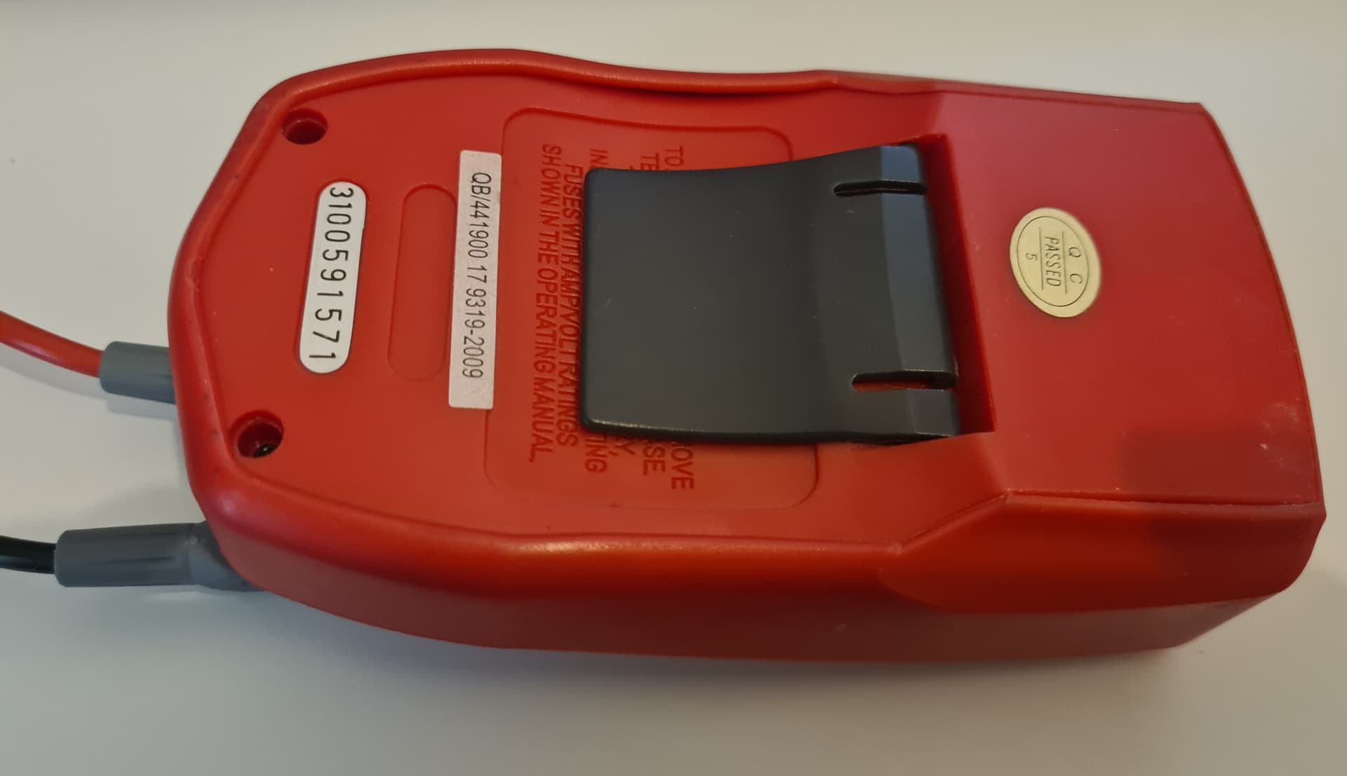
I think I still have some of the sensors around from the proto days in a box somewhere. I can hook one up if you need more data, but I’m afraid I’m late to this party…