I’ve got a small little .ino program for a Teensy 3.1 mcu that allows it to provide an i2c device, a uart port, and gpio. The program functions as a CTF game of sorts with configurable parameters at the start of the code. It would be easily expandable to add other functionality. the i2c device the Teensy presents to the BP5 are just simulated.
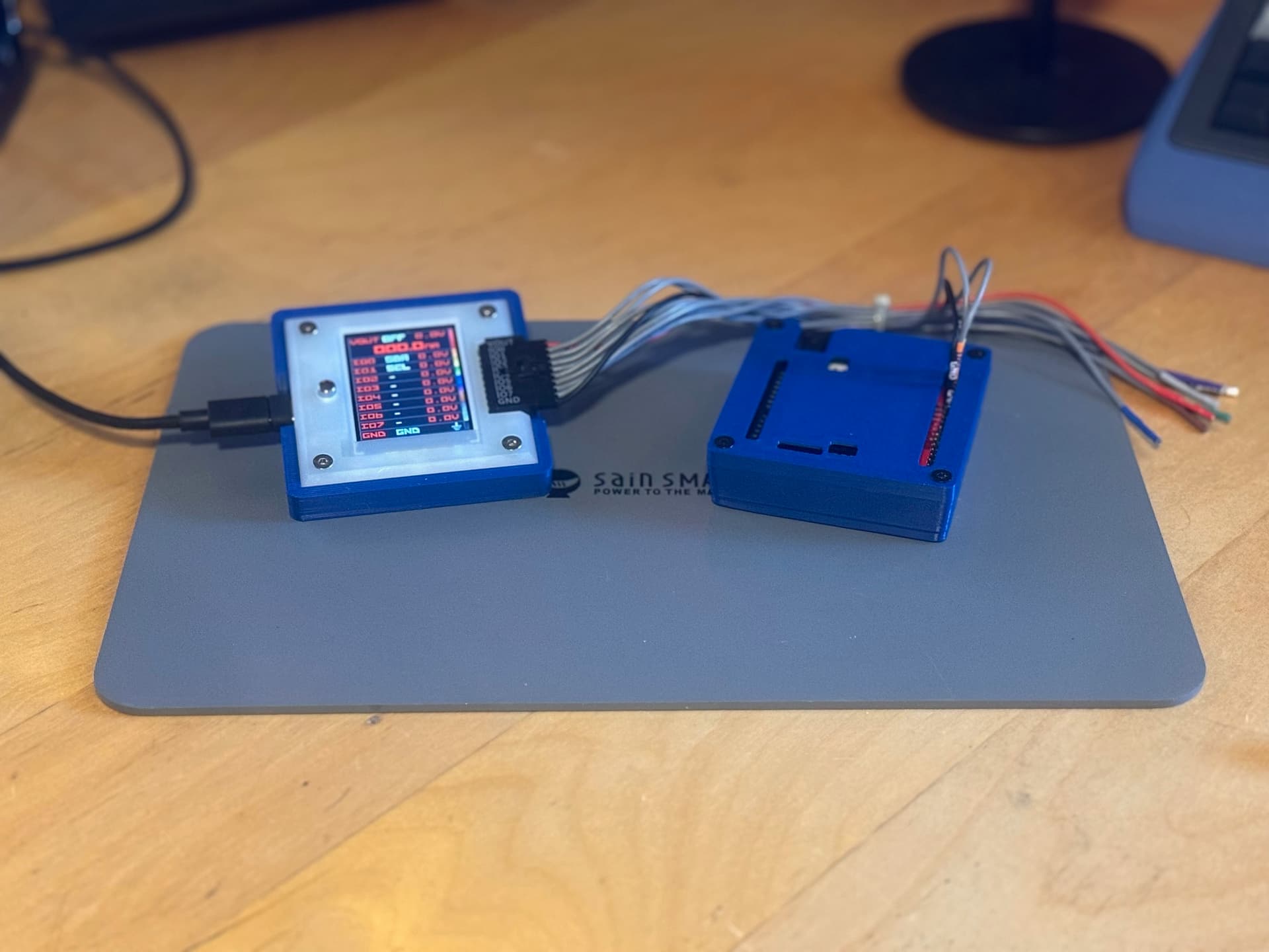
Thanks, Ian. I should have mentioned that I’m using a Teensy 3.x adapter board from SparkFun. The only modification is substituting SIP pins for the standard SIP header. I’ve also designed a 3D-printed case with magnets on the bottom to complement the setup. Along with that, I created a 3D-printed slanted base for the Bus Pirate 5, also featuring magnetic mounting. Together, they work quite well. I kept both models compact to fit in my carrying case alongside the rest of the kit. I’ve updated the GitHub repo with links to the 3D print files.
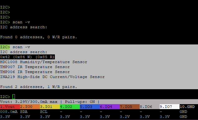
One odd thing that I see when doing i2c> scan -v.. I see what I think are just phantom i2c devices, because in the code, only a device at address 0x42 should show up. I haven’t searched here to see if this is common but I’ll do that. Otherwise things seem to work great. Glad you like it.
This library is included with the Teensyduino addon for the Arduino ide so my guess is your not using a Teensy 3.1? Either way, the last line in that points you in the right direction, I2C_SLAVE not declared in this scope. That is defined in the i2c_t3 library. Add that and you should be good.
Since PJRC decided to move its operations to Sparkfun, I’ve noticed that many Teensy-specific parts are consistently out of stock. I really hope that Sparkfun isn’t planning on killing off Teensy.
If I weren’t so inept, I’d try to rewrite it to use Wire. I started, but my ancient, Alzheimer’s-riddled brain vetoed that idea. I’m ordering a 3.2 from PJRC.
The problem is that the wire library doesn’t support slave node with i2c, so a library for this would still be needed. There are a few. There is also a fork of i2c_t3 library for the t4 but they seem unsupported at the moment. I’ll look at this this weekend. Not tough to convert as most of the code is already done.
I may not be seeing what you are seeing, or perhaps the UI could be clarified. Your image shows a single device at 0x42. I believe (but am not certain) that it then shows you four device types that are commonly found at that address. But at the end, it confirms a single R/W address pair was found.
I don't think that you're wondering why it shows two addresses...
I2C defines the address as the 7 most significant bits, and the least significant bit as an indicator of which direction the data should flow.
If you instead consider the entire byte as the address, then there’s a pair of addresses that start with an even number … that’s still one device.
0x42           Device address (hex)
0b0100'0010    Device address (binary)
0b1000'010x    7-bit address with 'x' for data direction
0b1000'0100    7-bit address for write commands == 0x84
0b1000'0101    7-bit address for read  commands == 0x85