I’ll post further updates to the 1-Wire, I2C, SPI, etc unified EEPROM command in this thread.
TODO:
Handle write/verify gracefully when file is longer or shorter than EEPROM size. Handle partial page write gracefully by reading current page and overwriting region.
Partial page writes are now handled properly. Most I2C and SPI EEPROMs can do partial page writes, but not all. 1-Wire eeproms cannot, and a full 8 or 32 bytes need to be written each time. This is all handled below the hood, so the user doesn’t need to worry about anything.
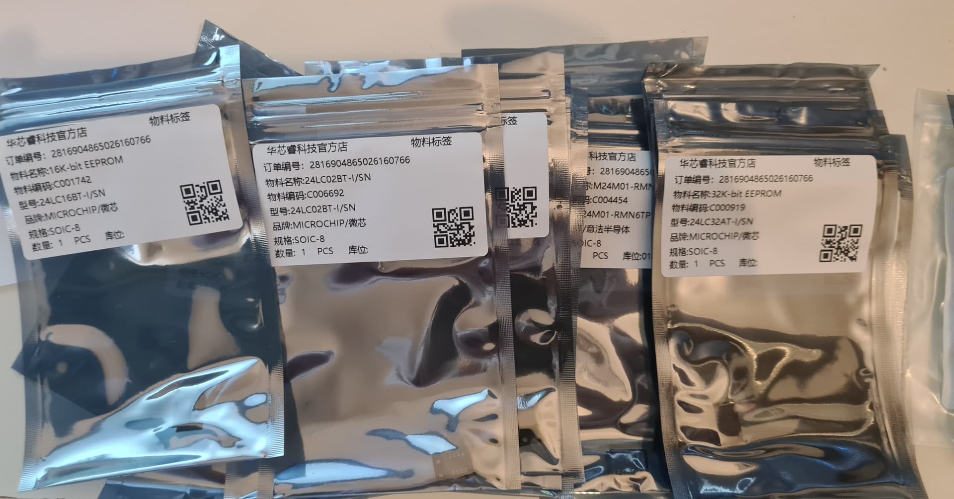
If you have any EEPROMs I’d appreciate some test reports! I have only tested with 24x02, 25x020, and DS2431. It will be a miracle if I managed to add full catalogs of EEPROMs without a single bug.
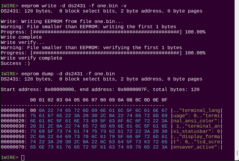
Bugs aside, it seems like this is the end of the work on EEPROMs for now. Not sure why I decided now was the time to add this, and it took over the last week or so. The results, especially the updated hex viewer, are super spiffy though. Much more professional and easier to read.
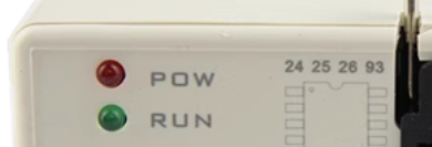
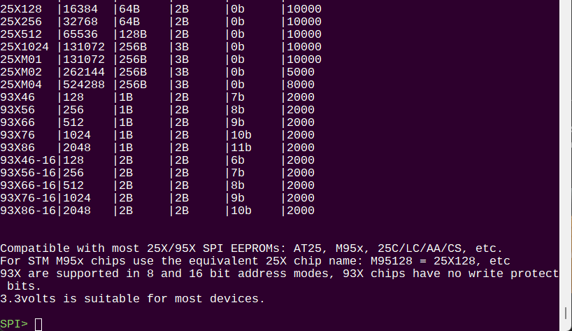
I should have studied some existing programmer instead of brute force building my own list of devices Came across one of these universal programmers on Taobao, and reading the compatible device list was really illuminating.
Aside: In an effort to ape the competition this programmer lists “26” devices all over the sales material. No such device is listed in the supported parts, and in fact I can’t seems to find any EEPROM with a 26x designation. They also list “95” which is really just STM’s name for the common 25x. Gotta collect them all!
Device
Type
Mode
25Q
SPI Flash
SPI
25x (& “95x”, by STM)
SPI EEPROM
SPI
24x
I2C EEPROM
I2C
93x
Weird SPI EEPROM
3WIRE
Thus far we have:
SPI flash command for 25Q (among others) flash memory
SPI EEPROM command for 25X EEPROMs. I read every STM M95 EEPROM datasheet and confirmed they can be used with the equivalent 25x device settings.
I2C EEPROM command covers all the 24x I2C EEPROMs I can find
93x is an older EEPROM, but it’s still around so I want to add support as well
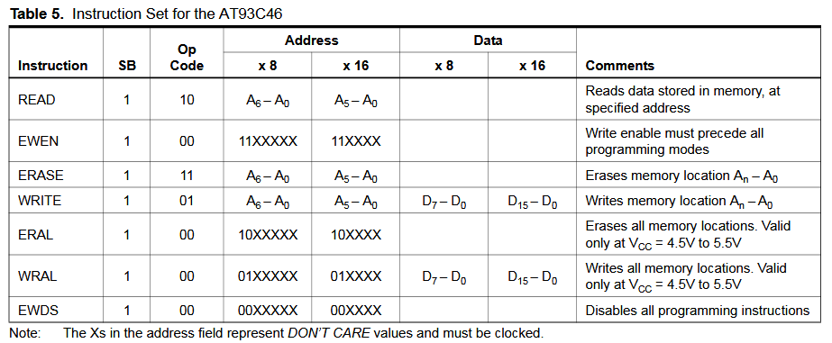
93x is weird, mainly because it doesn’t use 8 bit bytes. It won’t work with most standard SPI peripherals without some funny business.
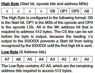
Start bit required (1bit)
Op code is the command to execute (2 bits)
A 7 or 6 bit address, depending on 8 or 16 bit read/write mode pin
A single 8 or 16 bit word for each write
Continuous reads seem to be supported
In 8 bit mode the command/address is 10 bits, in 16 bit mode it takes 9 bits. Neither align with the standard 8 bit data read/write format of the data word.
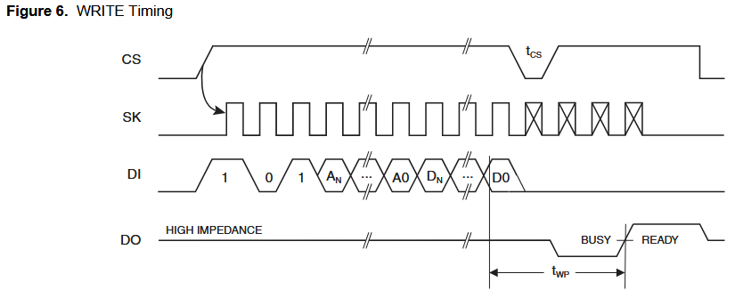
Here’s the write sequence. Start bit (1) opcode (01) address (6 or 7 bits), 1 data word. Busy is indicated by raising CS after >tCS (250ns) and waiting while DO is low (so use pull-up resistor).
Device
Size
Bytes
Organization
Dummy bits
Address
Total bits
93x46A
1Kbit
128
x8 only
0
7bits
10
93x46B
1Kbit
128
x16 only
0
6bits
9
93x46C/E
1Kbit
128
x8 or x16
0
7 or 6bits
10 or 9
93x56A
2Kbit
256
x8 only
1
8bits
12
93x56B
2Kbit
256
x16 only
1
7bits
11
93x56C
2Kbit
256
x8 or x16
1
8 or 7bits
12 or 11
93x66A
4Kbit
512
x8 only
0
9bits
12
93x66B
4Kbit
512
x16 only
0
8bits
11
93x66C
4Kbit
512
x8 or x16
0
10 or 9bits
12 or 11
93x76A
8Kbit
1024
x8 only
1
10bits
14
93x76B
8Kbit
1024
x16 only
1
9bits
13
93x76-/C
8Kbit
1024
x8 or x16
1
10 or 9bits
14 or 13
93x86A
16Kbit
2048
x8 only
0
11bits
14
93x86B
16Kbit
2048
x16 only
0
10bits
13
93x86-/C
16Kbit
2048
x8 or x16
0
11 or 10bits
14 or 13
x8 or x16 bits is selected by the ORG pin. If ORG is low, the device is x8, if ORG is high, the device is x16.
Total bits = Start Bit (1) + Opcode (2) + Dummy bits (0/1) + Address bits
Here are the potential devices, at least the Microchip and Atmel range: 46/56/66/76/86. A parts are fixed 8 bit words, B are 16 bit words, and C have a ORG pin that determines the organization.
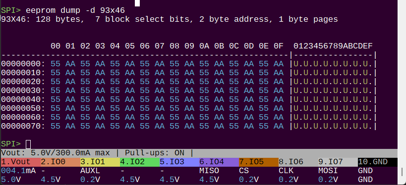
93x EEPROM support integrated into the SPI mode eeprom command. This took a rework of how the hardware abstraction layer works, but the result has an improved structure.
This is untested for now as I don’t have any 93x EEPROMs to test against. Some are on the way.
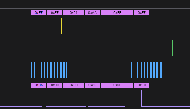
This is technically a Microwire EEPROM, not SPI, but it is really close. RP2040 has a Microwire mode, but it seems WAY more involved than SPI. When enabled it’s sending double the data I intend plus weird changes on MOSI, probably the normal SPI way of using it doesn’t apply.
The data is coming out of the chip, but the RP2040 can’t see any of it.
Maybe I can just change the clock phase before reads?
    hwspi_deselect(); // deselect the EEPROM chip NOTE: 93X are CS active HIGH
    hwspi_set_cphase(0);
    hwspi_write_n(address_array, 2); // send the address bytes
    hwspi_set_cphase(1);
    hwspi_read_n(buf, read_bytes); // read bytes from the EEPROM
    hwspi_select(); // select the EEPROM chip NOTE: 93X are CS active HIGH
    hwspi_set_cphase(0);
Got it I just needed to manipulate the clock phase between write and read. Will need to store the current setting and restore after I guess.
What an annoying little thing, and it’s so old demonstration projects for RP chips are non existent.
Now I will continue verifying all the chips in 8 and 16 bit modes.
ETA:
Evidently the app note was clear. I assumed the pic had different settings for read and write clock phase, but that clearly just says to switch it.