I’ve received recently my BP5 and experiencing a strange behavior.
Initially I couldn’t connect over the serial port, but this was fixed by flashing the latest firmware.
Now the self test is failing, because it can’t detect the USB voltage.
Also, when I apply voltage on IO0 it is detected on both IO0 and IO4. Same thing for:
IO1 and IO5
IO2 and IO6
IO3 and IO7
I guess there is something wrong with the analog multiplexing, as if the AMUX_S2 addressing input is stuck at high level.
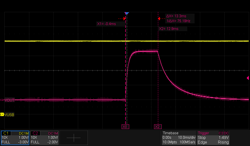
So, I’ve checked it with a scope, but I see toggling on the addressing inputs of the multiplexer.
Sporadically, on a good day, the issue disappears and it works as expected.
Any advice? Thanks.
This is the self test log:
Screen Resolution changed
HiZ> iThis device complies with part 15 of the FCC Rules. Operation is subject to the following two conditions: (1) this device may not cause harmful interference, and (2) this device must accept any interference received, including interference that may cause undesired operation.
Bus Pirate 5 REV10
https://BusPirate.com/
Firmware main branch @ 08daec6 (Apr 8 2025 14:49:45)
RP2040 with 264KB RAM, 128Mbit FLASH
S/N: 2B2C385F68A863E4
Storage: 0.10GB (FAT16 File System)Configuration file: Loaded
Active binmode: SUMP logic analyzer
Available modes: HiZ 1WIRE UART HDUART I2C SPI 2WIRE 3WIRE DIO LED INFRARED JTAG
Active mode: HiZDisplay format: Auto
HiZ> ~
SELF TEST STARTING
DISABLE IRQ: OK
ADC SUBSYSTEM: VUSB NOT DETECTED (0.03V). ERROR!
FLASH STORAGE: OK
PSU ENABLE: PSU ERROR CODE 2
VREG==VOUT: 25 = 25 OK
BIO FLOAT TEST (SHOULD BE 0/<0.30V)
BIO0 FLOAT: 0/0.04V OK
BIO1 FLOAT: 0/0.04V OK
BIO2 FLOAT: 0/0.04V OK
BIO3 FLOAT: 0/0.04V OK
BIO4 FLOAT: 0/0.04V OK
BIO5 FLOAT: 0/0.04V OK
BIO6 FLOAT: 0/0.04V OK
BIO7 FLOAT: 0/0.04V OK
BIO HIGH TEST (SHOULD BE >3.00V)
BIO0 HIGH: 0.04V ERROR!
BIO1 HIGH: 0.04V ERROR!
BIO2 HIGH: 0.04V ERROR!
BIO3 HIGH: 0.04V ERROR!
BIO4 HIGH: 0.04V ERROR!
BIO5 HIGH: 0.04V ERROR!
BIO6 HIGH: 0.04V ERROR!
BIO7 HIGH: 0.04V ERROR!
BIO LOW TEST (SHOULD BE <0.30V)
BIO0 LOW: 0.04V OK
BIO0 SHORT->BIO1 (0.04V): ERROR!
BIO0 SHORT->BIO2 (0.04V): ERROR!
BIO0 SHORT->BIO3 (0.04V): ERROR!
BIO0 SHORT->BIO4 (0.04V): ERROR!
BIO0 SHORT->BIO5 (0.04V): ERROR!
BIO0 SHORT->BIO6 (0.04V): ERROR!
BIO0 SHORT->BIO7 (0.04V): ERROR!
BIO1 LOW: 0.04V OK
BIO1 SHORT->BIO0 (0.04V): ERROR!
BIO1 SHORT->BIO2 (0.04V): ERROR!
BIO1 SHORT->BIO3 (0.04V): ERROR!
BIO1 SHORT->BIO4 (0.04V): ERROR!
BIO1 SHORT->BIO5 (0.04V): ERROR!
BIO1 SHORT->BIO6 (0.01V): ERROR!
BIO1 SHORT->BIO7 (0.04V): ERROR!
BIO2 LOW: 0.04V OK
BIO2 SHORT->BIO0 (0.04V): ERROR!
BIO2 SHORT->BIO1 (0.04V): ERROR!
BIO2 SHORT->BIO3 (0.04V): ERROR!
BIO2 SHORT->BIO4 (0.04V): ERROR!
BIO2 SHORT->BIO5 (0.04V): ERROR!
BIO2 SHORT->BIO6 (0.05V): ERROR!
BIO2 SHORT->BIO7 (0.04V): ERROR!
BIO3 LOW: 0.04V OK
BIO3 SHORT->BIO0 (0.04V): ERROR!
BIO3 SHORT->BIO1 (0.04V): ERROR!
BIO3 SHORT->BIO2 (0.04V): ERROR!
BIO3 SHORT->BIO4 (0.04V): ERROR!
BIO3 SHORT->BIO5 (0.04V): ERROR!
BIO3 SHORT->BIO6 (0.03V): ERROR!
BIO3 SHORT->BIO7 (0.05V): ERROR!
BIO4 LOW: 0.04V OK
BIO4 SHORT->BIO0 (0.04V): ERROR!
BIO4 SHORT->BIO1 (0.04V): ERROR!
BIO4 SHORT->BIO2 (0.04V): ERROR!
BIO4 SHORT->BIO3 (0.04V): ERROR!
BIO4 SHORT->BIO5 (0.04V): ERROR!
BIO4 SHORT->BIO6 (0.05V): ERROR!
BIO4 SHORT->BIO7 (0.05V): ERROR!
BIO5 LOW: 0.04V OK
BIO5 SHORT->BIO0 (0.04V): ERROR!
BIO5 SHORT->BIO1 (0.04V): ERROR!
BIO5 SHORT->BIO2 (0.04V): ERROR!
BIO5 SHORT->BIO3 (0.04V): ERROR!
BIO5 SHORT->BIO4 (0.04V): ERROR!
BIO5 SHORT->BIO6 (0.05V): ERROR!
BIO5 SHORT->BIO7 (0.04V): ERROR!
BIO6 LOW: 0.04V OK
BIO6 SHORT->BIO0 (0.04V): ERROR!
BIO6 SHORT->BIO1 (0.04V): ERROR!
BIO6 SHORT->BIO2 (0.04V): ERROR!
BIO6 SHORT->BIO3 (0.04V): ERROR!
BIO6 SHORT->BIO4 (0.04V): ERROR!
BIO6 SHORT->BIO5 (0.04V): ERROR!
BIO6 SHORT->BIO7 (0.05V): ERROR!
BIO7 LOW: 0.05V OK
BIO7 SHORT->BIO0 (0.04V): ERROR!
BIO7 SHORT->BIO1 (0.04V): ERROR!
BIO7 SHORT->BIO2 (0.04V): ERROR!
BIO7 SHORT->BIO3 (0.04V): ERROR!
BIO7 SHORT->BIO4 (0.04V): ERROR!
BIO7 SHORT->BIO5 (0.04V): ERROR!
BIO7 SHORT->BIO6 (0.08V): ERROR!
BIO PULL-UP HIGH TEST (SHOULD BE 1/>3.00V)
BIO0 PU-HIGH: 0/0.04V ERROR!
BIO1 PU-HIGH: 0/0.04V ERROR!
BIO2 PU-HIGH: 0/0.04V ERROR!
BIO3 PU-HIGH: 0/0.04V ERROR!
BIO4 PU-HIGH: 0/0.04V ERROR!
BIO5 PU-HIGH: 0/0.04V ERROR!
BIO6 PU-HIGH: 0/0.05V ERROR!
BIO7 PU-HIGH: 0/0.04V ERROR!
BIO PULL-UP LOW TEST (SHOULD BE <0.30V)
BIO0 PU-LOW: 0.04V OK
BIO0 SHORT->BIO1 (0/0.04V): ERROR!
BIO0 SHORT->BIO2 (0/0.04V): ERROR!
BIO0 SHORT->BIO3 (0/0.04V): ERROR!
BIO0 SHORT->BIO4 (0/0.04V): ERROR!
BIO0 SHORT->BIO5 (0/0.04V): ERROR!
BIO0 SHORT->BIO6 (0/0.04V): ERROR!
BIO0 SHORT->BIO7 (0/0.05V): ERROR!
BIO1 PU-LOW: 0.04V OK
BIO1 SHORT->BIO0 (0/0.04V): ERROR!
BIO1 SHORT->BIO2 (0/0.04V): ERROR!
BIO1 SHORT->BIO3 (0/0.04V): ERROR!
BIO1 SHORT->BIO4 (0/0.04V): ERROR!
BIO1 SHORT->BIO5 (0/0.04V): ERROR!
BIO1 SHORT->BIO6 (0/0.05V): ERROR!
BIO1 SHORT->BIO7 (0/0.04V): ERROR!
BIO2 PU-LOW: 0.04V OK
BIO2 SHORT->BIO0 (0/0.04V): ERROR!
BIO2 SHORT->BIO1 (0/0.04V): ERROR!
BIO2 SHORT->BIO3 (0/0.04V): ERROR!
BIO2 SHORT->BIO4 (0/0.04V): ERROR!
BIO2 SHORT->BIO5 (0/0.06V): ERROR!
BIO2 SHORT->BIO6 (0/0.04V): ERROR!
BIO2 SHORT->BIO7 (0/0.04V): ERROR!
BIO3 PU-LOW: 0.04V OK
BIO3 SHORT->BIO0 (0/0.04V): ERROR!
BIO3 SHORT->BIO1 (0/0.04V): ERROR!
BIO3 SHORT->BIO2 (0/0.04V): ERROR!
BIO3 SHORT->BIO4 (0/0.04V): ERROR!
BIO3 SHORT->BIO5 (0/0.04V): ERROR!
BIO3 SHORT->BIO6 (0/0.05V): ERROR!
BIO3 SHORT->BIO7 (0/0.05V): ERROR!
BIO4 PU-LOW: 0.04V OK
BIO4 SHORT->BIO0 (0/0.04V): ERROR!
BIO4 SHORT->BIO1 (0/0.04V): ERROR!
BIO4 SHORT->BIO2 (0/0.04V): ERROR!
BIO4 SHORT->BIO3 (0/0.04V): ERROR!
BIO4 SHORT->BIO5 (0/0.04V): ERROR!
BIO4 SHORT->BIO6 (0/0.05V): ERROR!
BIO4 SHORT->BIO7 (0/0.05V): ERROR!
BIO5 PU-LOW: 0.04V OK
BIO5 SHORT->BIO0 (0/0.04V): ERROR!
BIO5 SHORT->BIO1 (0/0.04V): ERROR!
BIO5 SHORT->BIO2 (0/0.04V): ERROR!
BIO5 SHORT->BIO3 (0/0.04V): ERROR!
BIO5 SHORT->BIO4 (0/0.04V): ERROR!
BIO5 SHORT->BIO6 (0/0.04V): ERROR!
BIO5 SHORT->BIO7 (0/0.05V): ERROR!
BIO6 PU-LOW: 0.05V OK
BIO6 SHORT->BIO0 (0/0.04V): ERROR!
BIO6 SHORT->BIO1 (0/0.04V): ERROR!
BIO6 SHORT->BIO2 (0/0.04V): ERROR!
BIO6 SHORT->BIO3 (0/0.04V): ERROR!
BIO6 SHORT->BIO4 (0/0.04V): ERROR!
BIO6 SHORT->BIO5 (0/0.04V): ERROR!
BIO6 SHORT->BIO7 (0/0.05V): ERROR!
BIO7 PU-LOW: 0.04V OK
BIO7 SHORT->BIO0 (0/0.04V): ERROR!
BIO7 SHORT->BIO1 (0/0.04V): ERROR!
BIO7 SHORT->BIO2 (0/0.04V): ERROR!
BIO7 SHORT->BIO3 (0/0.04V): ERROR!
BIO7 SHORT->BIO4 (0/0.04V): ERROR!
BIO7 SHORT->BIO5 (0/0.04V): ERROR!
BIO7 SHORT->BIO6 (0/0.04V): ERROR!
CURRENT OVERRIDE: PPSU CODE 2, ERROR!
CURRENT LIMIT TEST: OK
PUSH BUTTON (ANY KEY SKIPS): OK
RELEASE BUTTON (ANY KEY SKIPS): OKERRORS: 7
FAIL!HiZ>
1.Vout 2.IO0 3.IO1 4.IO2 5.IO3 6.IO4 7.IO5 8.IO6 9.IO7 10.GND
OFF - - - - - - - - GND
0.0V 0.0V 0.0V 0.0V 0.0V 0.0V 0.0V 0.0V 0.0V GND