Tested the demo on the small SPI flash board presented here:
W25Q64 SPI flash board | Bus Pirate 5 Firmware
Cant manage to see any 0x02 response on the Status Register - tried on multiple board pieces …
1 Like
That’s a nice looking logic analyzer! I typically only see Seleae and Sigrok these days, that looks like a nice alternative.
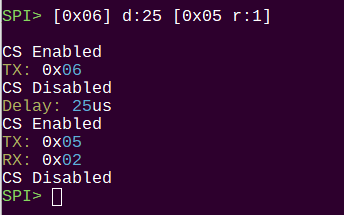
Is the preceding command [0x06] to enable writes in the status register?
1 Like
Hi Ian,
Yes DL16/Plus is Sigrok friendly , also can add custom protocol decoders in Python.
Sure [0x06] was executed previously …
Do you get 0xff if you try to read for any location? If it doesn’t read anything out, then I’d check the power and connections.
@Dreg any thoughts?
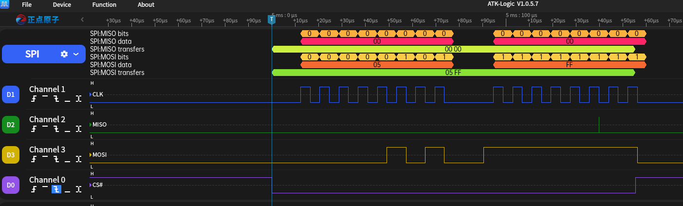
I did a 256 bytes write and then read at addr 0000 but read back values do not match what I wrote ! (not FFs but garbage data) … something is going really bad there … 0x00 values - page write then read is only working fine …
Does the garbage read back match what the logic analyzer sees?
Everything looks good on the logic plot. Speed seems right, the commands are there.
Yes it does match with the LA waveforms but it does not match with intended data which was written at address … ![]()
It makes sense if you can’t confirm the write enable bit that the data wouldn’t read back.
Is it the same board DREG used in the tutorial? Is it possible the write protect needs to be pulled high?
Its the exact board presented in the demo foto (W25Q64).
Yes WP# and #HOLD are properly pulled up. checked with multimeter.
Just in case, what do you see on the logic analyzer (flash chip side) if the MISO/CDI pin is disconnected from the Bus Pirate? I just want to rule out a defective buffer chip interfering with the line.
@kokoshell What firmware are you using? Is it the latest? I’ll test with the latest firmware tomorrow
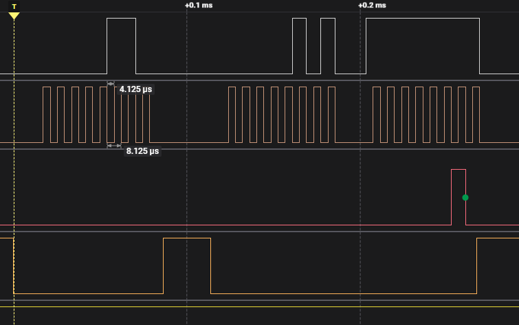
Tested now with latest build … main-8224b5c. There seems to be a periodic glitch on MISO (you can see one in LA screenshot above). T = 282 miliseconds …

Something really crazy is there … I can see the glitch on the CLK as well …
Put the MISO line on oscilloscope (removed LA probe) …nothing there !

Thank you for the update. I will investigate with the latest firmware.
There is a new firmware with two small adjustments. I don’t think it had the best glitch fix.
This should not effect the chip responding to the command though in most circumstances. To be sure, the AMUX is now disabled during syntax execution.
However, the last logic plot with two glitches at the same time, and one changing the clock from high to low is something different. I’m not sure what to make of that. Is it possibly the interaction with bus hold in the logic analyzer buffer? I have that issue with my logic analyzer.
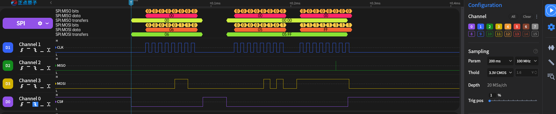
I don’t have that exact chip or board, but here’s a similar chip with the same command set using the latest firmware.
Hi Ian, still not working for me with the latest FW, will have a look on the MISO line on connection board …
Thank you for the update. There is a little spike there again.
If you disconnect MISO from the bus pirate and watch the flash DO pin with the LA we might see something. That could be a stuck buffer.
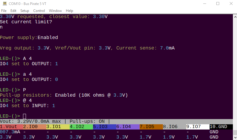
You can go into a mode that doesn’t use those pins (led?) and try to manipulate IO4:
- LED mode, onboard LED
- W to enable power (3.3volts)
- A 4 (CDI high output) should show 3.3v on the pin
- a 4 (CDI low output) should show 0v on the pin
- P to enable pullups
- @ 4 (CDI input, read) should be 3.3v/1
1 Like