7REV1+ ideas SPI ADC, IO expander, roadmap

Thanks.

Looking really nice the layout, good work by your layout expert. Fancy 45° ICs.

I had a very short look and these are the points I suggest to change:

  • 1.15 core voltage LDO
  • 100k pullx instead of 1M
  • Power/5V of the TVS diode at the USB-C connector should go before the ferrite, not after
  • Power/5V should be routed more directly to the TVS diode at the USB-C connector. Route the data lines to the left of it, then the power trace can directly go to the power area near the USB-C connector that comes before the ferrite.

Both points are to catch ESD impulses as early as possible, before they have a chance to go into the board.

Nothing is exploding. Will keep it that way until the samples arrive at my doorstep and I subject them to destructive limit testing.

2 Likes

I have seen that you don’t have a 3D model for the PSRAM. I have attached the one I’ve been using for my Winbond NOR flash, you can use that too.

I can’t 100% guarantee all dimensions, but it looks reasonable to me.

USON-8_UX_2x3x0p6_WIN.zip (17.7 KB)

2 Likes

I was honestly surprised the 3D was done at all :slight_smile: Supul must have done that because it was patchy before. I’ll add this, I’m looking at your change list now.

3 Likes

Something like this?

Seems to fit.

I’ll probably want Supul to clean this up. When you don’t have more changes I’ll hit him up to do a final placement and cleanup.

3 Likes

Regarding the TVS at the USB-C socket:

yes, like this. Changing the pin assignment works even better than my suggestion.

Maybe turn it 45° clockwise and move it up a bit? Then the cap could go more near to the vusb_raw. But this is just fine-tuning now.

Regarding the TLV75801PDRVR 1.15V LDO:

I suggest 2 changes:

  • move the 10µ output cap below the regulator to reduce the loop area between the output cap and GND. This is no switcher, but good layout always helps. See also the layout suggestion in the datasheet.
  • Add a feed-forward capacitor. It is not strictly required, but it will improve regulation. The datasheet doesn’t show it in the example schematics, but mentions it several times. In the layout example it is also shown. They have a separate appnote where they explain that it helps. Since this is for eventual overclocking and going near the limits, we want all the regulation improvements we can get to prevent core voltage droops during load spikes and such. Regarding Cff value: For the AP2127 we use 120pF, I think using the same value here would be ok.

2 Likes

This evening I did one measurement on my 7Rev0 I wanted to do:

Measuring the filter for ADC_AVDD of the RP2350.
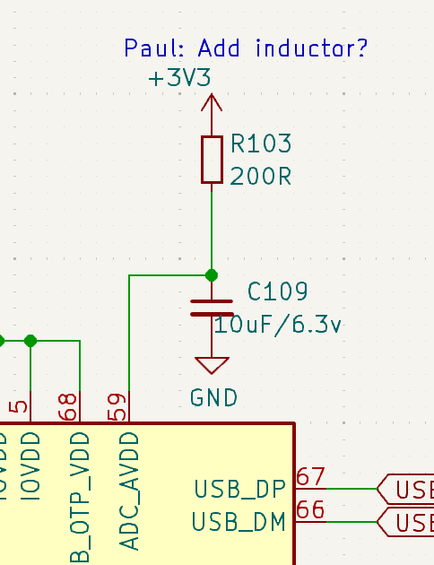
Current setup:

Measured voltages (with a warmed-up K 2001 no less):

3.3V rail: 3.3159V (0.48% off nominal)

AVDD in bootloader: 3.3158V
AVDD with regular BP firmware: 3.2891V
AVDD in scope mode: 3.2853V

→ Current drawn in scope mode: 153 µA

So the RP2350 clearly has a current draw on AVDD that changes with load, and the more ADC sampling you do, the more current is drawn. In scope mode we are 30.6 mV off, that is about 0.93%.

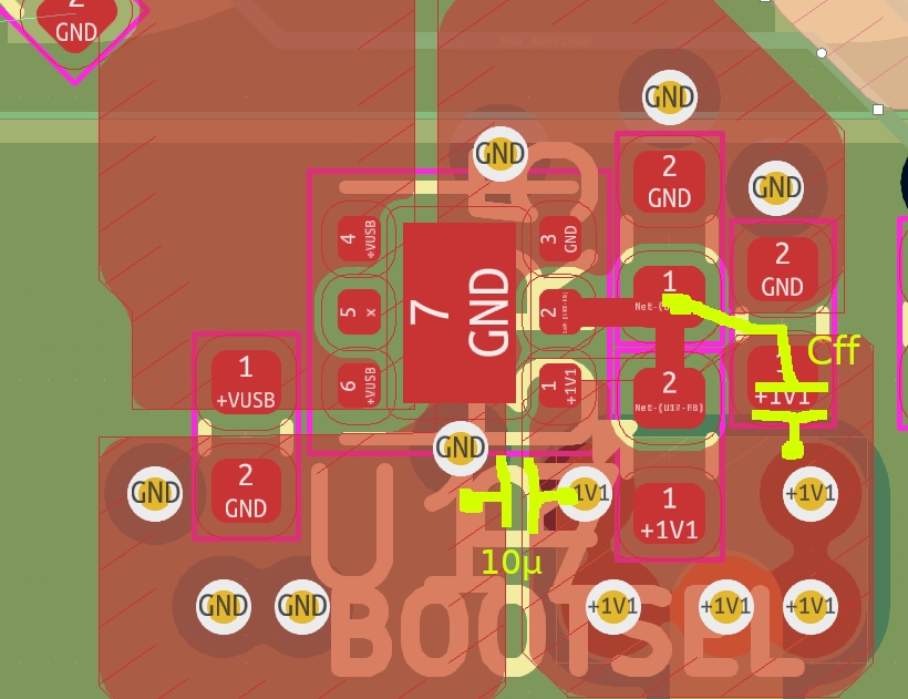
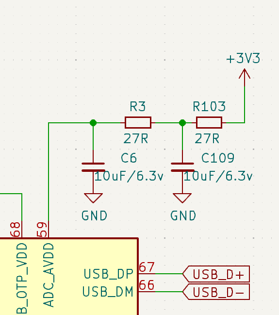
This is not deadly, but I think this is wasted accuracy and it can be mitigated easily by improving the filter like this:

The 27 Ohms are already used on the board, so no extra BOM line.

The 153 µA would now just cause a voltage drop of 8.3 mV, improving the inaccuracy caused from 0.93% to 0.25%.

How will the new filter affect noise on AVDD?

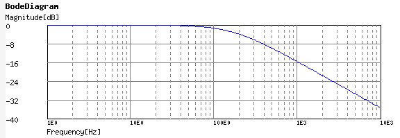
Let’s start with the filter as it was in Rev6 (as filtering there was most probably ok): Single order RC-filter with 200R and 4.7µF.

http://sim.okawa-denshi.jp/en/CRtool.php

Gives us a -3dB frequency of 169 Hz and the graph to 10 kHz looks like this:

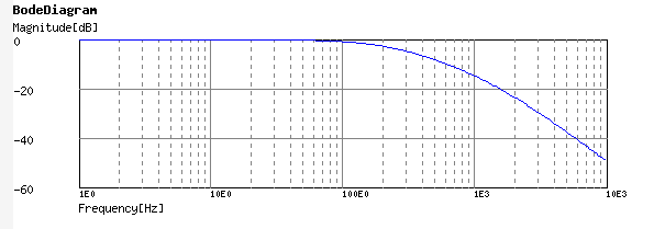
The new filter is a second-order filter with steeper rolloff.

http://sim.okawa-denshi.jp/en/CRCRtool.php

-3db freq is a bit worse with 589 Hz.

But higher frequencies are filtered much better because it is a second-order filter:

At 1 kHz it is about the same as the previous filter, above it becomes much better.

Since usually the slightly higher frequencies are what cause issues and not the stuff below 1 kHz, I think we also get an improved filtering with this change.

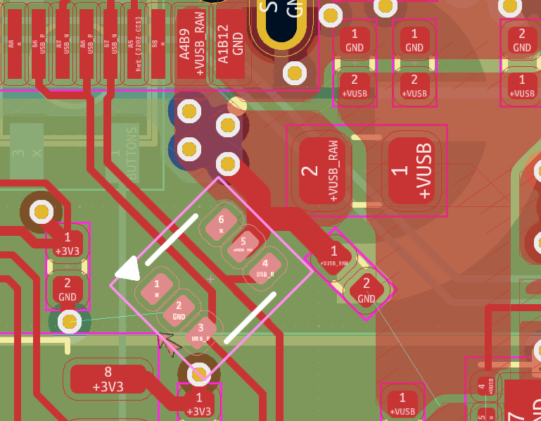
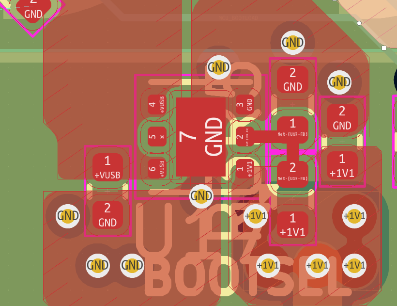
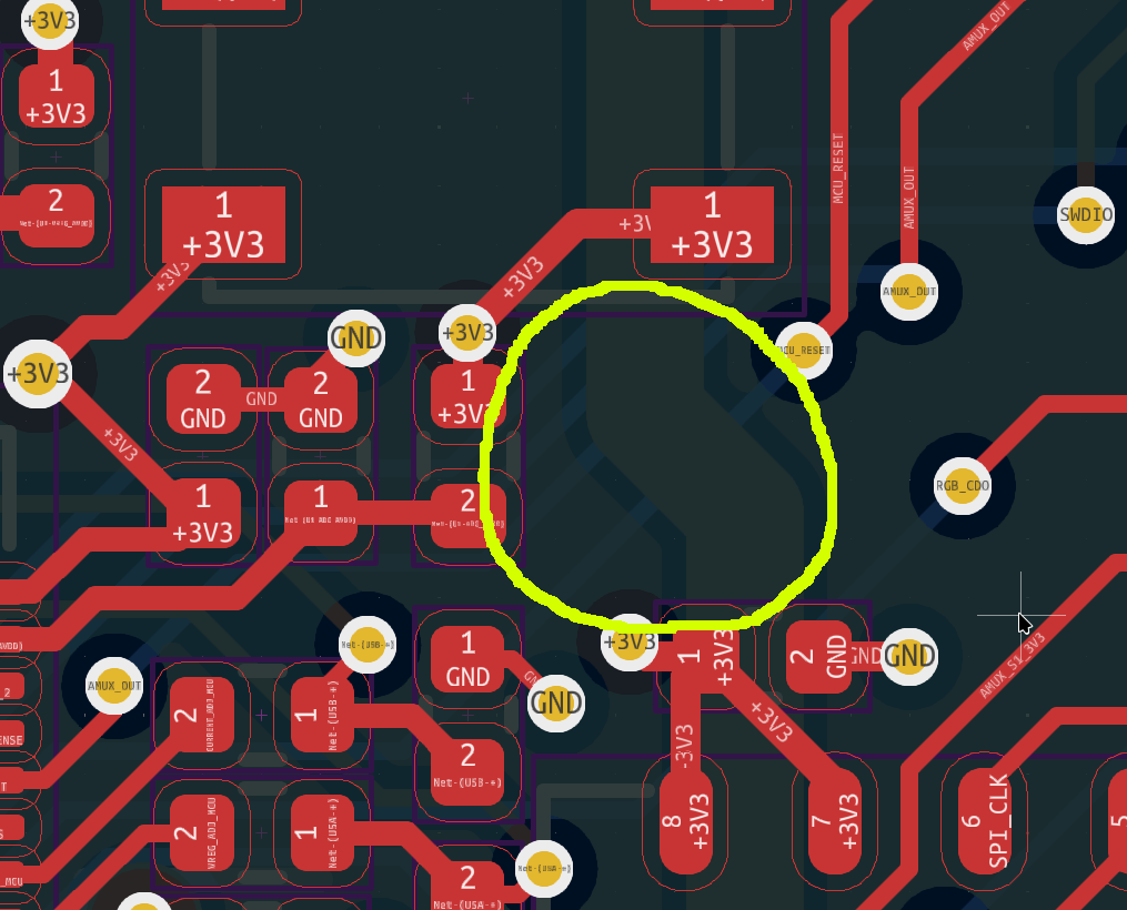
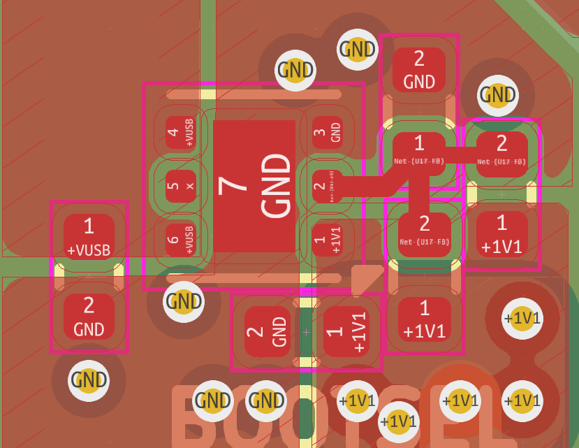
When I look at the layout I think there is space left for the two extra parts:

So this would be another change I suggest for 7Rev1. Then we can test if it is really an improvement or not.

3 Likes

Implemented this change, thank you.

Do you have thoughts on the core voltage and resistors to use? I imagine the values should be optimized so we get the best accuracy. Are we shooting for an initial 1.15V, or sticking with 1.1 and testing others manually?

2 Likes

After they later raised the guaranteed speed of the RP2040 I also suspect that they will sometime do the same with the RP2350. Raising the voltage a bit, but not into dangerous levels, will probably also be done for this case.

When you plan with the user having to manually change the voltage with resistors it will make firmware much more complicated. The slightly increased current consumption and warming when directly using 1.15 is something that I think isn’t an issue with the way the BusPirate is designed and used.

So I think directly raising the voltage from the start in preparation for higher speeds in the future is the best course of action here.

How about 110k / 100k as resistors? This will give nominal 1.155V and is clearly below the threshold the datasheet gives regarding Ifb.

If I did not miscalculate, this will give us between 1.143 and 1.169V when using 1% resistors, just for the voltage divider. The 0.7% of the voltage regulator come on top. I think this is still a reasonable range for this application. But maybe you can get some better tolerance resistors for cheap?

2 Likes

Thank you, that makes sense. I updated the schematic.

0.1% resistors don’t break the bank, but they are very pricey. 0.5% is very doable.

KiCAD project uploaded as archive.

The PCBs have been sent for production, sourcing for new parts will probably happen Monday.

1 Like

Did you not like my suggestions regarding the layout for the 1.15V LDO and the feed-forward capacitor or did you forget to add them?

Also the outline of the pcb seems to be malformed now. The check complains and the 3D view doesn’t show the outline.

1 Like

I completely forgot, I’m sorry. I added it and replaced the gerbers in production.

Yes, that is due to the frame for PCBA. I’m not sure how to fix that, we usually just move it to the eco2.user layer until production.

1 Like

Thanks. Could you push the latest version you used to github?

So your fab doesn’t have a problem with the data in this form, correct?

I can take a look and check if I find a way to do this without Kicad complaining.

1 Like

Pushed to same place.

It’s never been a problem at any fab, which is why we just kind of left it that way.

1 Like

I exported all the fabrication files. We’ll get these going by the end of the week.

Question about the resistors arrays for pullx. In the past I assumed the arrays were only available in 5%, but I see some in 1% now. Would the additional accuracy be useful for impedance testing?

How about the 120R/0.5W. If it is useful for the pull-x resistors it is probably useful on the pin series resistors as well.

I’m not sure how much this will affect the accuracy. The impedance testing will probably be just a rough guess, because the internal resistances of ICs, like series resistances and pulls, are non-linear most times. For example a CMOS stage will usually not have a real series resistor, but implement a current limited FET instead.

Also some kind of self-calibration with the voltage regulator, ADC and switching in different voltage dividers would probably be possible.

On the other hand if the prices are like regular resistors, where the difference between 1% and 5% often is just in the 3rd or 4th digit, then I’d say go for 1%.

The 120R are always in series to the pins. But the 120R are small compared to the pulls we have and the general accuracy I expect for the impedance measurement. So they won’t have a huge influence on the final result. On the other hand these resistors should be rated for pulse loads because they are part of the port protection scheme. This means they should be thick film resistors and these are often not as precise as thin film ones.

So I would focus more on resilience than on precision here.

1 Like

Thank you so much.

1% are 3 to 6x more expensive, but I doubt that adds up to 0.01usd per board.

I will ensure the 120s are pulse rated, thank you. It’s probably going to be a major brand, I’m working on sourcing those now.

1 Like

Yeah, resistors. Luckily they are cheap.

Does Uni-Royal count as a major brand?

These are the ones I tested:

1 Like

Well, then, yes :slight_smile:

I saw that part but thought they might be a bit cheap. Szlcsc has replaced a bunch of the family specific resistor data sheets with the full catalogs, so I’m digging through them now. If I had more paper I would probably print them out, it feels faster.

Today I also added a szlcsc part number field to the kicad footprint spreadsheet thing. Now we can use their bom tool to order all the passive cuts for assembly. It costs a tiny bit more, but they bag and label it and that can go straight to PCBA. Saves a lot of annoying work for Ru.

1 Like

I don’t know how they compare to ones from Vishay or similar. But I got them to smoking hot for a minute or so, the solder got flowing, they would have fallen off if they were facing downwards. They survived and got back to their nominal value after cooling off. I’d say that is good enough for our purposes.

You mean an additional field in the Kicad part properties? Did you push this?

I have seen that these fields in the schematics are a bit convoluted right now. Some have a manufacturer, some not, some a linked datasheet, some not, and sometimes a wrong one. Would have spared me a few questions here in the forum if I could have relied on the info there, like manufacturer, exact part number and/or LCSC number.

I think these fields are quite handy when they are populated correctly. Kicad did really some good work in this area. You can open the datasheet with a hotkey. Also these fields can be shown and linked in an exported PDF.

The links should probably all go to a copy in the repo at github to withstand manufacturers being manufacturers and changing their websites.

1 Like