The chips also support I3C, so now I have a target to get I3C mode going.
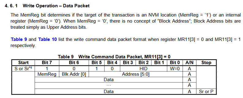
Thank goodness for small Asian manufacturers who actually include an explanation of the spec in the datasheet rather than blithely assuming you know THE SPEC. This is the same for flash SFPD tables. Winbond: nope, Puya: detailed explanation.
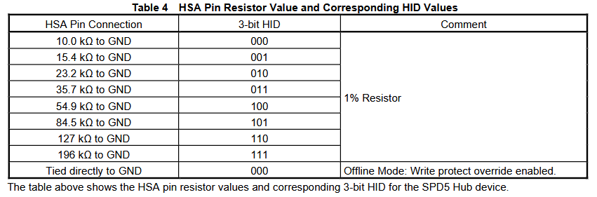
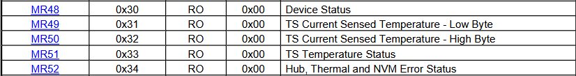
Resistor values used to set the I2C address via the HSA pin. The address is 0b1010000x, so 0x50 (0xa0, 0xa1) is actually the EEPROM. Weird, it behaved like one, but I find out later that there is a mode that causes the EEPROM read pointer to reset after a stop to reduce I2C bus traffic. Maybe it was that.
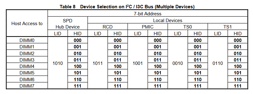
The second address is indeed a pass-through to another chip on the board. It looks like 0b1001000n is indeed a pass through to the PMIC. Cool. Now where do we get the datasheet for that chip…
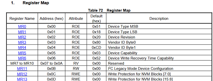
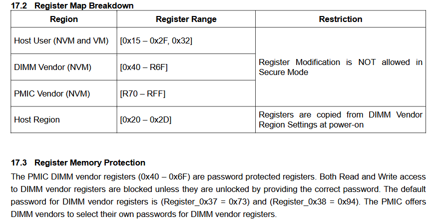
Super excited about this. There is evidently a vendor ID region, but it’s protected by a whole 2 byte passcode! I may have overlooked other security features, but I look forward to making an app to brute force this.
The resistor R2 for your LED is 2k. I had R12 at 6.8k because that is a value that is reasonable for the super-bright green LEDs I normally use. But if 2k works better for your normal LEDs then I suggest to change R12 to 2k too.
Yes, directly attaching it to the BP could cause mechanical issues. Some kind of wire would make more sense and the probe cables already come with all (most?) BPs, so using them makes sense.
How about small standoffs on all 4 sides of the DIMM plank PCB? Just that the bottom doesn’t sit directly on the table and could short with something conductive there. Like the tin foil we’ve seen dreg use on the table. Maybe use the small screw-in standoffs you have for one of the planks already (was it the RS232 one or the IR? don’t remember right now).
I will update the resistor value. I use 2k because I have a reel of them, not because it’s the right value.
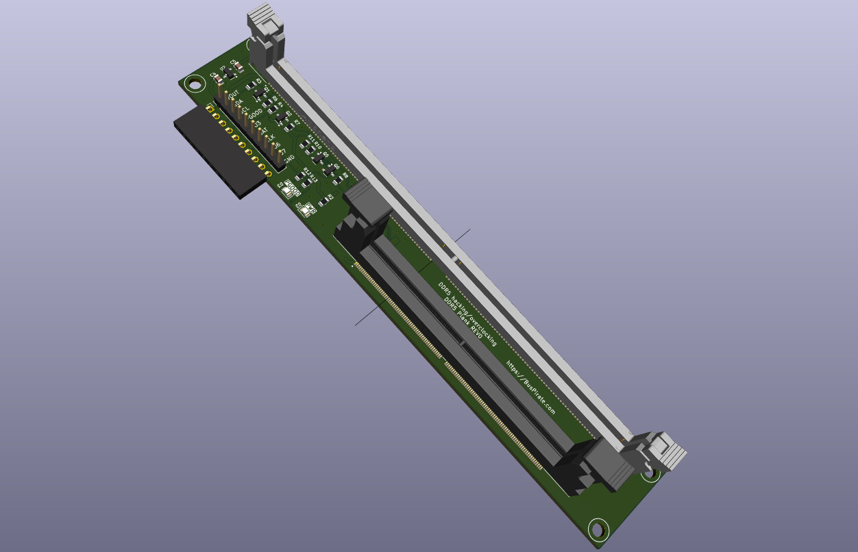
Routing should be ready tomorrow. There will be standoffs on the 4 corners. We debated a T shape to reduce weight and bulk, but then it would wobble on the legs.
That right angle female connector will be populated with male header. I prefer my wires to exit the board from the side. Vertical wires tend to be a bit annoying in general, and will probably cause this narrow board to tip over.
Boards done, just waiting for the parts to arrive.
The only “generic” SODIMM socket I can find is still pretty expensive, ~$4. In the interest of keeping a low cost version available, a UDIMM only version (SODIMM socket not populated) might be a good option.
You seem to have gone with direct attach which is fine. I was thinking putting QWIIC/STEMMA on the memory board might find it a larger audience. A plank with QWIIC/STEMMA also seems like a good choice for other reasons.
Am wondering if all the cheap ones are horizontal mounted (which would make the PCB more expensive).
If you want a master to compare with AMD/Xilinx have i3c in Vivado now.
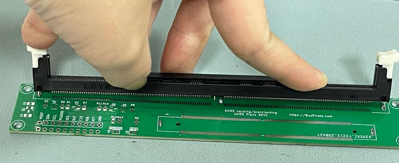
We’re using a male pin header for the connector, not the female connector shown in the render. Direct attach of a board this big would be awkward.
The horizontal SODIMM is defo the cheapest and most common. I’ve only found one supplier that stocks a vertical SODIMM connector. Another supplier asked if we’ve been calling around because they’ve been getting calls from other suppliers about vertical SODIMM sockets (it was not us, this was our first contact). Must be some demand then.
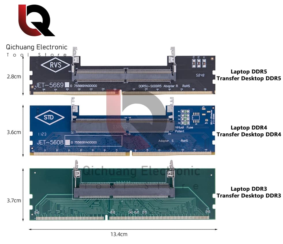
The adapter is an option. When I surveyed Aliexpress to see the most common cheap sockets making it to the world market I saw a lot of those. When I checked them on Taobao and 1688 it seems like the DDR5 adapter is more expensive than the socket we sourced.
It’s that problem where I want it to be as complete as possible and cover all scenarios. In reality desktop UDIMM is probably the widest use case, and SODIMM hackers can just BYO adapter. It doesn’t make sense to add a $10 premium for a feature few will use. Just a hunch though, I don’t actually know that to be the case.
I’m not so sure about SODIMM not being that common.
Laptops use SODIMMs and mini-pcs too. Both are very common form factors. Maybe desktops tend to be the preferred platform for ram hacks. But I’ve seen quite some hacks for mini-pcs too in the last few years. Like modding GPUs to connect them or >= 10 GBit network adapters to use them for storage and so on. So playing with their ram doesn’t seem too unusual to me.
If you are really on a budged you could always solder wires directly onto the DIMM and hook up the BP that way. So I would prefer the plank to offer the more complete solution, even if it is a few bucks more.
The adapters are an additional risk of getting some incompatible parts or a bad connection.
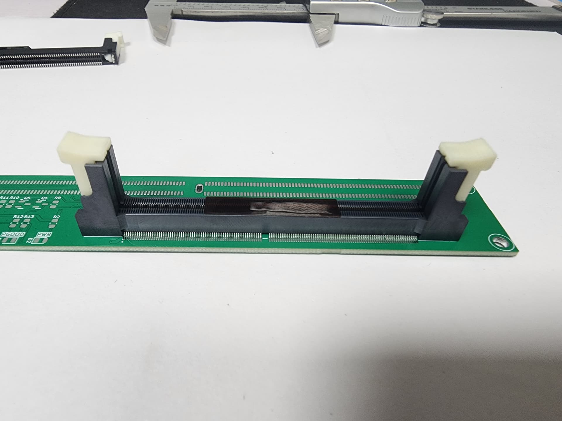
I ordered a LOTES UDIMM socket and the supplier sent me a datasheet screenshot. I checked the KiCad footprint against the supplier datasheet and everything looked perfect!
PCB shows up today and the socket doesn’t fit, almost like it’s mirrored. Checked the datasheet again, it seems fine. A morning of back and forth with the Shenzhen office and the supplier, the day before a holiday. Nobody is happy.
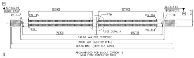
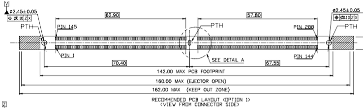
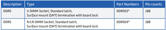
When I get the UDIMM datasheet I realize the KiCad footprint is actually RDIMM too. The only tell is this table at the end of the datasheet for the part.
Fortunately the only difference seems to be location of that center pin: left for UDIMM, right for RDIMM.
Footprint updated, gerbers sent out. It’s a holiday until next Wednesday, so it could be a while before the next revision is ready.
I haven’t planned doing server hacks with RDIMMs right now. But servers and big workstations are a field where vendors tend to play dirty tricks to grab more money, so maybe someone is interested in hacking there too.
How much more would it be to increase the PCB size to fit a RDIMM footprint on the PCB and just leave it unpopulated for now? To me it looks like this won’t be much, as it is just a 2 layer PCB.
That would allow anyone with server ambitions to solder on their own socket while other buyers don’t have to pay much more. If there is high demand for RDIMM hacking you could later easily populate the RDIMM socket too.
Interesting. It seems like the pinout is similar, but there’s a lot more secondary ics behind the SPD.
The PMIC has two supply inputs, a 3.3V VIN_Mgmt supply and the 12V nominal supply from the card edge through VIN_BULK. The VIN_Mgmt is used to generate the internal bias voltage for reading operation from its internal non-volatile memory content and to generate LDO voltages.
One issue is that vin is 12v on server version. However the data sheet I read says 4.5 to 12v, but the PMIC wants both a 3.3v supply (we have) and a 12v supply.
I admit I haven’t looked at the RDIMM specs. Adding things like a 12V supply and verifying the schematics is not worth the time for now. Let’s focus on getting it working with regular UDIMMs and SODIMMs first.
They all have some kind of standardish tables in the eeprom. The issue with sticks before ddr5 is that you need a 9volt programming voltage to make any changes. That’s not a huge deal, but I thought starting with the modern easier to hack stick was the best bet for a successful plank.