Firmware development updates

I agree with that. The workflow on my current project is to connect up the BP for UART, start bridge (or my new “glitch” command), and then power up the device and let the command execute.

In my personal branch I disabled the sanity checks to be able to do this.

1 Like
Mode FALA Syntax FALA Commands
1-WIRE :heavy_check_mark: :heavy_check_mark:
UART :heavy_check_mark: :heavy_check_mark:
HDUART :heavy_check_mark: :heavy_check_mark:
I2C :heavy_check_mark: :heavy_check_mark:
SPI :heavy_check_mark: :heavy_check_mark:
2WIRE :heavy_check_mark: :heavy_check_mark:
DIO :heavy_check_mark: :heavy_check_mark:
LED :heavy_check_mark: :heavy_check_mark:

Verification of the Follow Along Logic Analyzer in all modes is complete.

  • During the verification I spotted several small issues in several modes, be sure to get the latest firmware with the fixes
  • FALA bug when the capture buffer is full is fixed
  • All modes and mode commands have been updated and tested to support FALA

Immediate next steps:

  • INFRARED mode + IRTOY compatible binmode
  • Library of 3rd party firmware in a nice maintainable repo with autobuild (DirtyJTAG, etc)
  • Documentation updates (to v1 + scripting/macro/tutorial docs)
  • v1.0 celebration
2 Likes

I just reported a new minor bug in github, but one that I think is important to the 1.0 release. Beginners will copy/paste examples. In the process, they may copy an extra space. This causes a syntax error in the bus commands.
Example:

[]
 []

The second line causes a syntax error. This can cause confusion as someone may think they pasted the correct command from the example.

1 Like

I will add code to consume all leading spaces.

Pushed a fix for the space issue.

3 Likes

The latest Bus Pirate firmware has a number of fixes, and a new mode.

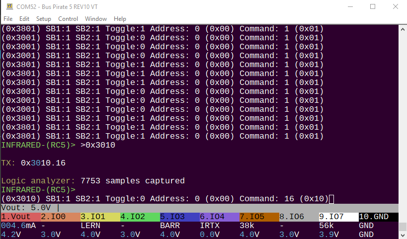
Infrared mode sends and receives NEC and RC5 remote control protocols. You’ll need to bring an IR LED and demodulator, or use something like the Infrared Toy plank. Soon I will add a binary mode compatible with LIRC (is that still a thing?), AnalysIR, etc.

An RTT debug channel is now available over the SWIO port.

I failed at my first attempt to port DirtyJtag to the Bus Pirate with a reusable “SDK”. I learned a lot about how it needs to be structured though, another attempt is on the way.

Fixes:

  • Logic command shows help when no options specified
  • Fixed several regressions in LED mode when using the onboard LEDs for the beginner tutorial. Additionally, the FALA will switch to the internal LED data out pin when using the onboard LEDs, so you can see what is happening (5 only, much more extensive changes needed to make this work on 6 that need some SDK bug fixes).
  • I2C mode demo commands general error handling and reporting improved
  • Tried to make the no pullups/no power warning less obnoxious in I2C and 1-wire mode
  • Whitespace (space characters) before syntax (>[or]) no longer cause an error
1 Like

I’m anxiously awaiting the AnalysIR compatibility.

2 Likes

There is a new 3WIRE mode, which is like SPI but you can manipulate the clock and MOSI pins independently using the /-_ syntax. This is useful for oddball devices that use reset, start bits, and opcodes that are not 8 bit bytes. For example, the 93LC66B uses a start bit and 2 bit opcodes which are not compatible with the typical 8bit I2C bus.

  • 3WIRE mode added
  • Fix display of bit commands /-_ state (2WIRE, 3WIRE)
  • New firmware timestamp format
  • Fixes during the initialization sequence, and ongoing improvements to deadlock situations (h/t @henrygab)
  • A factory mode to disable unique serial port numbers (h/t @henrygab)
  • Holiday mode (will expire in a week or so)
2 Likes

The latest firmware has some massive updates to infrared mode to get the IR Toy plank going:

  • 3 sub protocols: RC5, NEC, RAW
  • RAW reads/writes AIR timing packets that work with AnalysIR
  • irrx - Receive, retransmit, and save IR signals in AIR formatted packets
  • irtx - Transmit AIR formatted packets from the command line or a file
  • tvbgone - Plays 100+ TV “power off” signals to disable any obnoxious TVs in your vicinity
  • Updated flow of infrared mode configuration
  • Complete rewrite of raw IR signal handling, ready to be integrated with AIR binmode for AnalysIR RX/TX support
3 Likes

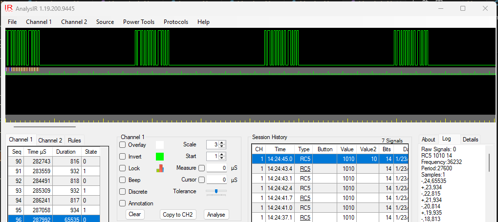
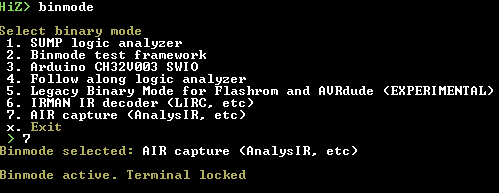
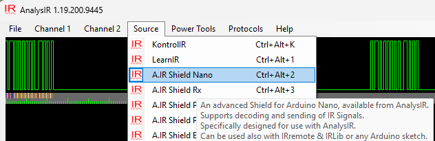
The latest firmware now supports AnalysIR, popular infrared signal analysis software for Windows. It is a paid program, with Educational, Maker and Pro versions available. Note that the free version does not support external hardware.

You will need an infrared demodulator and infrared diode, or use the IR Toy plank.

Use the binmode command and select the AIR capture mode.

Start AnalysIR and select A.IR Shield Nano as the source.

Now you can:

  • Press an infrared remote control button facing the IR demodulator to capture and analyze the signal
  • Select one of the captures and press CTRL+ALT+T to send that IR signal

If send doesn’t work, be sure that A.IR Shield Nano is selected as the source.

This is not free software. Our relationship with AnalysIR consists of the following:

  • There were multiple support requests here and on social media
  • I am grateful for the immense amount of support AnalysIR provided to perfect the IR plank and support the A.IR protocol
  • AnalysIR supports hardware I made in the past (IR Toy v1, v2)
7 Likes

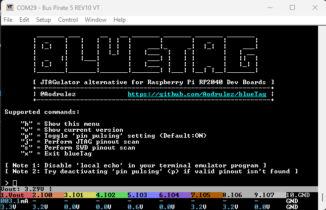
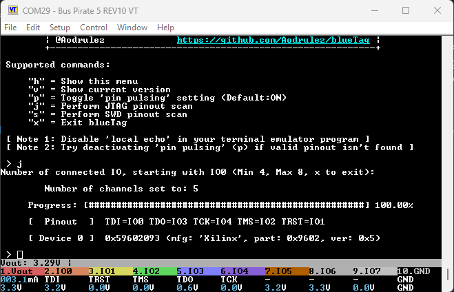
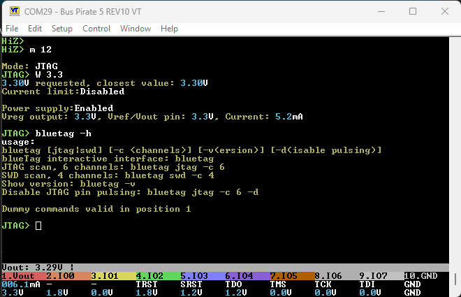
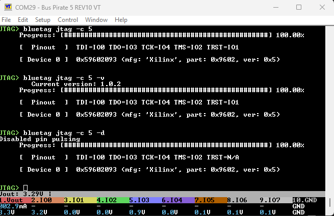
I’m about to post about the I2C sniffer, and see I missed a huge addition: bluetag JTAG and SWD pin finder is now integrated in the main Bus pirate firmware.

It can scan for both JTAG and SWD pins:

  • Enter JTAG mode
  • Enable a power supply
  • Use the bluetag command to access the blueTag interface.
  • Type s or j
  • Enter the number of connected pins, starting from IO0. I’m using IO0-IO4 (5 pins)
  • blueTag searches for a JTAG or SWD interface.

bluetag is also available from the Bus Pirate command line.

Command usage.

4 Likes

The latest firmware auto build supports I2C sniffing up to 500kHz via the pico-i2c-sniffer project.

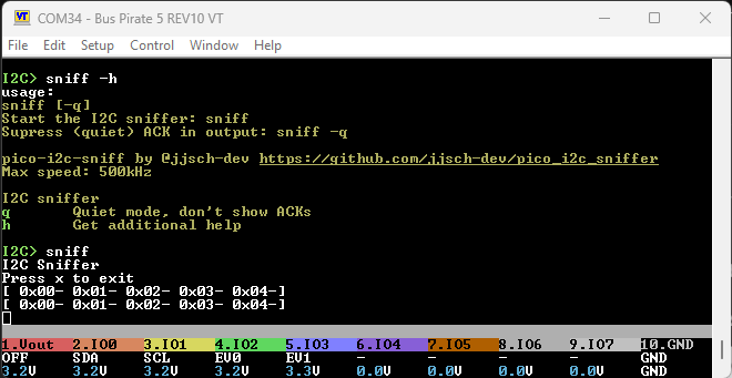
The output is similar to the I2C command syntax. Sniffed packets can be pasted into the command line and replayed.

The q quiet flag hides the ACK (+) indicator to make it easier to replay commands without editing the sniffer output. NAKs (-) will still be displayed.

Some preliminary documentation here.

2 Likes

A minor convenience change for the mode command.

m 5

You can already bypass the mode menu by specifying the mode number.

m i2c

Now you can also specify the mode by name (case insensitive). This should help scripts stay stable long term, even if the order of modes changes.

3 Likes

I think the mode: indication should probably be moved to the start of the output. Then we can consolidate the “XXX speed:” translation to a single “Speed:”. Will push asap.

Just a small style update to indicate the mode selection prior to mode configuration.

3 Likes

The last few months have been a lot of grunt work updating docs and tweaking features, but there some announcement worthy updates coming down the line!

DDR5 memory modules for computers have an Serial Presence Detect Hub chip that contains info needed to configure the SRAM. I2C mode has a new command ddr5 for working with SPD Hub chips. This can be useful for:

  • Rescuing a DDR5 stick with corrupted SPD data
  • Cloning “secret” keys inserted by manufacturers to lock equipment to their own RAM sticks
  • Just generally learning about SPD, which is pretty cool!

You’ll need an adapter and make some connections, but an easy to use plank is on the way!

SPD EEPROM JEDEC Manufacturing Information blocks 8-9:
  Module Manuf. Code: 0x859B (Crucial Technology)
  Module Manuf. Location: 0x00
  Module Manuf. Date: 22Y/04W
  Module Serial Number: 0xE6FFB785
  Module Part Number: CT8G48C40U5.M4A1
  Module Revision Code: 0x57
  DRAM Manuf. Code: 0x802C (Micron Technology)
  DRAM Stepping: 0x41

Searching Manuf. Specific Data area block 9:

@ 0x22B: 0x34 0x35 0x31 0x30 0x39 0x30 0x34 0x38 0x31 0x39 0x00 0x00 0x00 0x00 0x00 0x00 0x00 0x00 0x00 0x00

Searching End User Programmable Area blocks 10-15:

@ 0x280: 0x0C 0x4A 0x30 0x01 0x01 0x80 0xB3 0x01 0x02 0x00 0x00 0x00 0x00 0x00 0x34 0x38 0x30 0x30 0x20 0x43 0x4C 0x34 0x30 0x20 0x20 0x20 0x20 0x20 0x20 0x20 0x00 0x00 0x00 0x00 0x00 0x00 0x00 0x00 0x00 0x00

@ 0x2BE: 0x25 0x34 0x30 0x22 0x22 0x00 0x22 0xA0 0x01 0x7A 0x0D 0x00 0x00 0x00 0x00 0x00 0x41 0x80 0x3E 0x80 0x3E 0x00 0x7D 0x80 0xBB 0x30 0x72 0x27 0x01 0xA0 0x00 0x82 0x00 0x00 0x00 0x00 0x00 0x00 0x00 0x00 0x00 0x00

@ 0x2FB: 0x03 0x02 0x00 0xA2 0x3E 0x00 0x00 0x00 0x00 0x00 0x00 0x00 0x00 0x00 0x00

ddr5 probe shows the SPD Hub status and contents of the SPD Non Volatile Memory (EEPROM). It searches through the undefined block to find hidden info. Here we probably have Intel or AMD overclocking profiles in block 10-15.

I2C> ddr5 read -f backup.bin
Read SPD NVM to file: backup.bin
Device Type: 0x5118
Success :)
I2C> ddr5 verify -f backup.bin
Verifying SPD NVM against file: backup.bin
Device Type: 0x5118
Success :)

Of course you can read and verify the SPD contents.

I2C> ddr5 write -f backup.bin
Write SPD NVM from file: backup.bin
CRC verify
Stored CRC (bytes 510:511): 0xCB 0x72
Calculated CRC: 0xCB 0x72
CRC okay :)
Device Type: 0x5118
Write Protect Override is enabled: OK
Saving NVM block lock bits: 0xFF03
NVM block lock bits cleared: OK
Writing page 0
Writing page 1
Writing page 2
Writing page 3
Writing page 4
Writing page 5
Writing page 6
Writing page 7
NVM block lock bits restored: 0xFF03
Verify write
Device Type: 0x5118
Verify: OK
Success :)
I2C>

Finally, write to the NVM, with CRC check, block protection handing, and verification.

Documentation and adapter plank info should be up on the docs tomorrow.

3 Likes