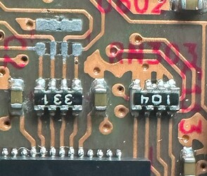
This applies to the first batch of Bus Pirate 5XL/6 that shipped around August 10th, 2024. All other boards are okay
The new RP2350-based Bus Pirates need an extra external pull-down resistor to fix silicon bug E9. We’re going to replace all the shipped boards, no need to do anything. However, here are some instructions if you’d like to try a fix.
Confirm the E9 bug
First, let’s confirm the E9 bug on your board. Download the latest firmware, disconnect anything from the Bus Pirate 10P header and then:
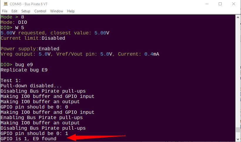
m 8- Enter DIO mode (or any mode where IO0 is not in use)W 5- Enable a power supply between 3.3 and 5 volts.bug e9- Run the bug command E9 test
The Bus Pirate will perform four tests. Test 1 and 2 confirm if E9 is found.
Resistor type and value
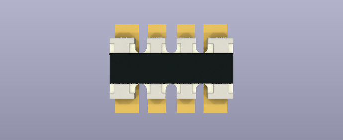
- 4.7K resistor array (4.7K-8K should all work)
- 4x0402 package (also called 0804 or 2010M)
- Convex type (pads on the end of the leads, not between the leads)
- These are usually 5%
- Generally 1/16th Watts, but not important in this application
Resistor array location
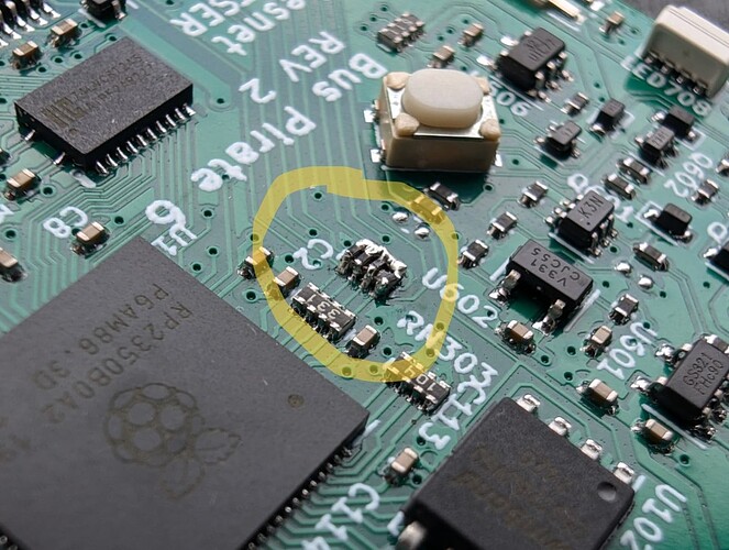
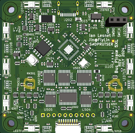
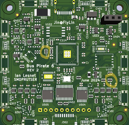
We need to replace the pull-down resistors on the RP2350 pins that control the Bus Pirate IO pins: RN302, RN307. Circled here on the 5XL and 6.
5XL resistor location.
6 resistor location
The fix
There’s at least three ways to apply the fix. Easy, Pro and Goblin mode.
Easy Fix
Instead of trying to remove the existing 100K pull-downs, we can leave them in place and solder the new resistor array on top. Arrays are usually 5% tolerance, so the 4.7K resistor value may vary by 235 Ohms. The extra 100K is almost nothing compared to the tolerance of the 4.7K resistors.
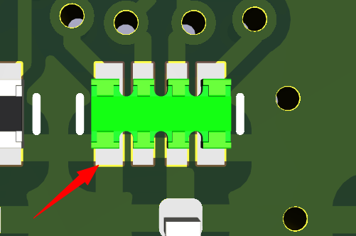
Look closely and find the side of the resistor array where all four leads connect together and to the ground plane. Start soldering on this side because it’s okay to be messy, and the thermal mass of the ground pad will keep everything in place while soldering the more sensitive side.
Start with the ground side. Hit it with flux and add a solder blob until everything is connected together. The pins all go to ground, so it’s fine if there are shorts between pads.
Now, hit the other side with some flux. Add a little solder at a time while heating the pads of both arrays. “The force” (surface tension) should keep the solder in the right place. If pads are shorted with too much solder, hit it with some more flux and gently remove the excess a little at a time with a copper wick. It’s easier than it looks, and all four pads can be soldered at once - the surface tension keeps the solder where it should be.
Pro Fix
Use a hot air rework tool to remove RM302 and RN307. Solder the new resistors on place.
I would argue this is the easier fix, but the LCD will burn easily so you need to know your stuff. I melt the LCD and need to replace it about 50% of the time I rework a Bus Pirate board.
You might be able to use a knife to gently cut away the 3M tape holding the display in place and then flip it away from the PCB. Be careful, that stuff is meant to last and often the LCD cracks in the process.
Goblin Mode Fix
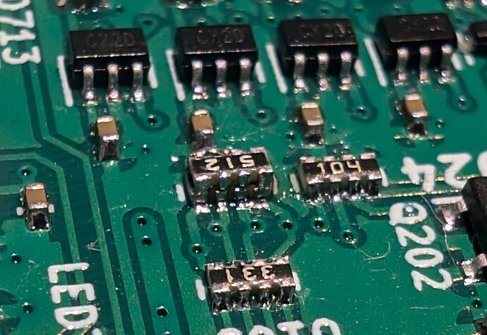
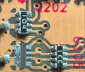
Not suggesting anyone try, but Matt at Blinkinlabs soldered four tiny 0201 resistors on top of the 4x0402 arrays to help us test this fix ASAP.
Test the fix
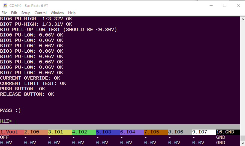
It’s probably a good idea to run the self test in HiZ mode using the ~ command. This will check for any shorts in the soldering.
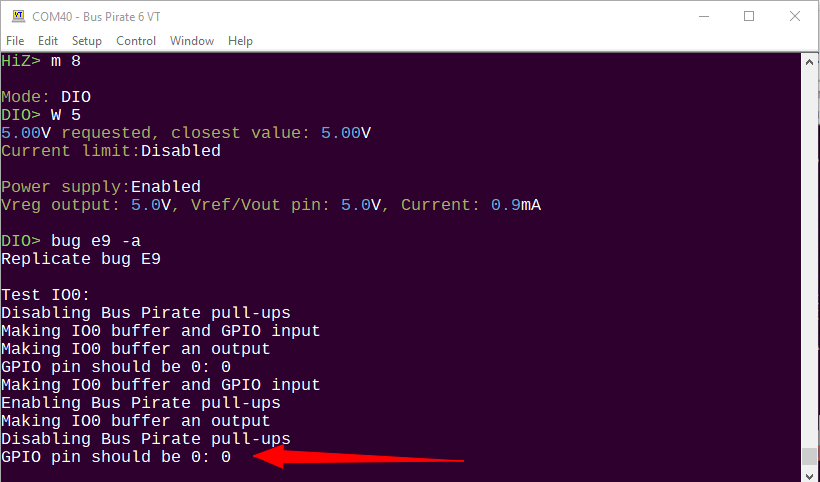
Finally, run bug e9 -a to confirm that the fix is working. Disconnect anything from the Bus Pirate 10P header and then:
m 8- Enter DIO mode (or any mode where IO0 is not in use)W 5- Enable a power supply between 3.3 and 5 volts.bug e9 -a- Run the bug command E9 test.-aruns the E9 test on all 8 IO pins
The fix worked if the GPIO pin is 0 after the test.
I Fixed My Six!
Post a pic of your Six Fix (or attempt) and I’ll send you this sticker!
