So I just got my self a v6, because my old v3 (which I had never actually used :-/) turned out to be defective : I couldn’t upgrade the firmware (LED didn’t turn on) and it didn’t even pass self test. never mind, I was more upset about UPS taking at least 13 days to deliver. BP6 is very nice, seems like I’m missing the rubber feet tho, and I was distracted by the sticker on the static pouch that said ‘5’ (so I opened the case to make sure it was a 6). was a little surprised by the number of buttons, I also feel they are too tall (but not a big deal), and yeah I definitely have enough allen keys that this could have been saved. I wonder how many kilotons of redundant allen keys are being shipped (and then discarded) in the world each year.
Anyway, back to the topic.
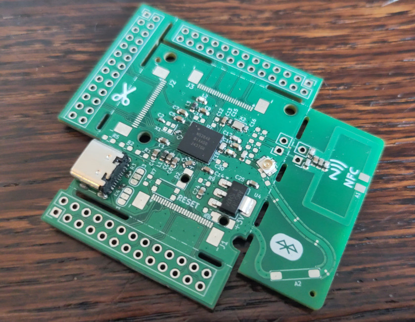
I created my custom board for an nRF52840 ; it’s very minimal and basically the reference circuit (from the datasheet), just about every pin is exposed (because I need this for a custom keyboard). My problem is that I don’t find how to flash a bootloader on my chip. I have found some info but it is not sufficient:
Nordic semi doc (see link in next post) also helps, but the nRF has SWDIO instead of separate DI and DO.
I would greatly appreciate to have some guidance with this. if required (meaning, unless I missed one that already exists) I will make a video about this step (I will be making some for my keyboard anyway, because I think it’s worth it and others have asked for it already)
ps: on Flashing a BIOS chip with Bus Pirate - DP it says that insulating the “tiny adapters below” is not easy with heat shrink. yes indeed: it’s much easier with hot glue
pps: BP6 is very pretty, like so pretty I’m going to let it hooked up to computer just for decoration
AFAIK the nRF52840 doesn’t come with a bootloader preprogrammed. So while you can flash a bootloader and then use that for future firmware updates, you need to connect via the SWD debug interface at least once to initially flash the bootloader. So if it is just you using your board you could simplify things and skip the bootloader.
So you need an SWD interface.
For the BusPirate there is for example the ported pico debug probe firmware, see Porting Pico Debug Probe . But I’m not sure if that already runs on a BP6, I think it is just ported to the BP5 yet.
Once you got that running you can use OpenOCD to connect to the nRF52840 SWD interface. Once the debug probe firmware runs on the BusPirate, it works just as any other CMSIS-DAP probe. So you should be able to follow other guides for using OpenOCD to flash nRF52840.
Electronic_eel is correct … no default UF2 bootloader exists for the nrf52840 … the UF2 bootloaders you might see (e.g., Adafruit nrf52840 Feather boards) are just part of the flash.
I’m very familiar with this chip (ported FastLED to work on it, long ago), and I’ve contributed heavily to the ghostfat implementation used by tinyUF2, which supports lots of boards that use tinyUSB.
Thus, if you use tinyUSB, you could likely also use TinyUF2 with low overhead. Just need a way at early boot to decide if need to load the UF2 code, or your normal firmware (e.g., a button held, pressed during boot, etc.).
AFAIK there is no bootloader ; out of 3 boards that have a USB connector, none registers anything in dmesg.
Either case, I need to flash something without a pre-existing bootloader. I’d rather flash a bootloader, because that makes future upgrades much easier. Also, that board I designed for the nRF is intended as some sort of dev kit so it would make sense to have a bootloader on it
The chips are almost certainly shipped blank without a bootloader.
If it has a SWD 2 wire debug interface then using OpenOCD to program the bootloader of your choice is probably the most direct route.
Unfortunately @electronic_eel is correct. There is a port of the debug probe for BP5 but not BP6. It is not a trivial update to the core pirate-lib, or I’d whip up a port for you right now. I can try to get it going in the next few days.
Did you get the enclosure v2 separately? Is that what lacked the feet? The packaged BP6 comes in enclosure v1, which doesn’t have feet.
The old Dangerous Prototypes “flashing a bios chip” tutorial you link is specific to programming common SPI NOR flash chips from Winbond and others. It does not apply to programming the flash inside a microcontroller.
sure, a bootloader makes sense for a kit. Look at the links from @henrygab .
Regarding flashing the bootloader via SWD: Before ian has time to finish porting the picoprobe firmware to the BP6, maybe you have some other hardware that you can use for this:
Do you happen to have any other CMSIS-DAP probe that you can use with OpenOCD?
Or a RasPi Pico or Pico2? Then you could flash the original picoprobe firmware onto it.
Another way (instead of OpenOCD) would be to use the Blackmagic Probe firmware. That works nicely for flashing microcontrollers in my experience. You can flash the Blackmagic firmware not only on dedicated Blackmagic Probe Hardware, but many development boards and similar. Have a look here, scroll down until ST-Link: Supported Hardware — Black Magic Debug documentation
Do you happen to have any other CMSIS-DAP probe that you can use with OpenOCD?
no, the only thing I had was the (apparently defective) BP3, I was about to purchase a Blackmagic probe but knowing a little about the BP and seeing how it had improved since BP3 I thought I might as well get the BP. I cannot afford an blackmagic probe in addition to the BP. Had I known there were these development barriers with BP6 I might have gotten BP5 :-s
Or a RasPi Pico or Pico2? Then you could flash the original picoprobe firmware onto it.
I don’t have any at hand, but I could briefly borrow one so I could work with that.
OpenOCD
I had never heard of it before, it surely needs some sort of hardware? Modern machines don’t even have a parallel port anymore…
Ok, I guess then this is the easiest route to success. Flash the debugprobe_on_pico.uf2 or debugprobe_on_pico2.uf2 (depending on version of the pico) from this repository:
Then your pico becomes a CMSIS-DAP probe.
OpenOCD is the most common program to access JTAG and SWD on linux. It supports many different kinds of probes to connect to JTAG and SWD ports. And CMSIS-DAP probes are one (very common) type of this.
I will try to bring up pico probe on BP6 tomorrow.
Indeed. If you want reliable BP5 is the ticket. We had a single reel of rp2350b to make BP6, it was a fun hardware challenge but 5 is still the baseline.
I would have appreciated if this had been made a little more obvious in the process of ordering ; I feel like I’m stuck with more junk (albeit pretty when powered on) that will never be used
I finally ot my hands on a Pico, I’ll see what I achieve with this now that I have some time to spare
After a lot of efforts (due in part to a known-to-work-but-turned-out-to-be-faulty USB cable) I was able to flash my Pico ; then I found Running (OpenOCD User’s Guide) that mentions openocd -f interface/ADAPTER.cfg -f board/MYBOARD.cfg which seems to be what I need next but I’m now struggling to find what the cfg files should contain… can someone please give me info on what I should put in my configuration files?
So the first part to select the probe would be: openocd -f interface/cmsis-dap.cfg
Depending on your OS and udev configuration you might have to add a sudo in front.
Then you got to select your target. I guess this should work by just adding -f target/nrf52.cfg. Then you should get a SWD connection.
I still need some assistance though… I checked I have 3V3 on the power rail, continuity on SWDIO and SWDCLK was checked as well, but I get Error: Error connecting DP: cannot read IDR
I read sth about access port protection but since the chip is brand new and was (supposedly) never flashed with anything, this shouldn’t be the issue, right?
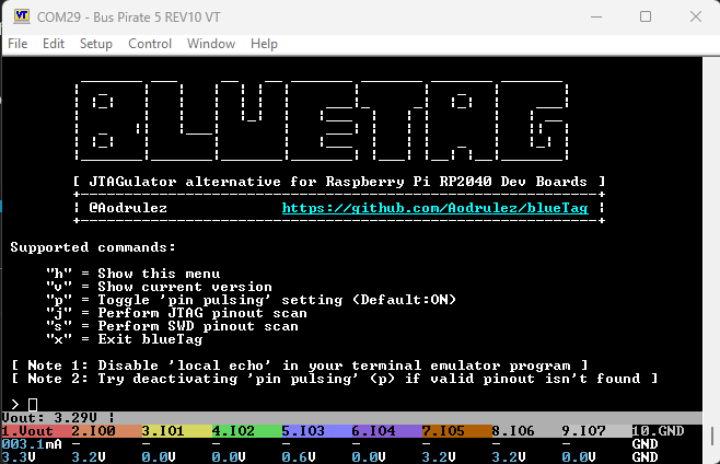
You could try to probe the SWDIO pins with the bluetag command in JTAG mode. It doesn’t depend on any particular software & config files, it just pushes generic commands into all combinations of pins.
It will search all possible combination of pins for a SWDIO port
I’m really sorry to hear you feel that way. To be clear though, JTAG debugging is not a supported or advertised feature for any current Bus Pirate version.
There are experimental ports of a few 3rd party firmwares that can do JTAG on the Bus Pirate hardware, which is going to become part of larger library of alternate firmware for the Bus Pirate. This is still a work in progress, and will support all hardware versions when it is officially released.
If there is anything in the documentation or sales pages that suggests JTAG debugging is currently supported please let me know. I don’t want to cause any confusion.
it doens’t suggest it, but it definitely doesn’t make it obvious. something like a table of features across all versions and revisions of the BP would be great.
so anyway, you’re suggesting to use to bluetag feature that is obviously not on the BP6 I have. this is very disappointing. also, I made the target board, I have the schematic and PCB files, so I’m pretty sure which pin is which (or else I really need some help, but not from here). the PCB was designed after the manufacturer’s design, so it should work, right? unless I’m missing something.
since BP5 is still the baseline, is there a chance the get my brand new and never used BP6 exchanged for a BP5? what I really don’t want is to pay the outrageous 50$-or-so customs fees that are VAT + the tax the carrier takes