Welp, you summed up my thoughts precisely!
3 Likes
One more thing I noticed, with corresponding change request:
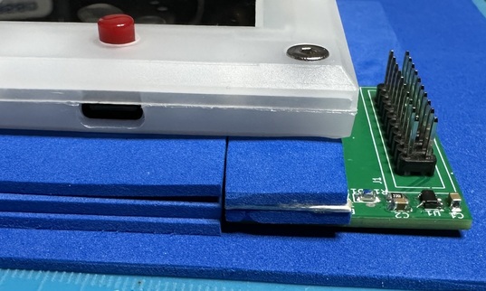
Where the PCB is flat on a surface, I’m trying to place the buspirate on, it’s not intuitive / easy to get the alignment right. Many times, I seem to get the pins stuck between the header and the case. Since the PCB has all this empty space on top…
- Fit’n’Finish … Can you add silkscreen lines for where both the Case v1 (and Case v2) corner and edges (with labels, if different) should line up on the top of the PCB?
And I am really starting to think that those wide bases should be embedded in the PCB (using a larger hole … not a standard via). Or maybe this is additional evidence of my level of sanity. ![]()
3 Likes
Using only 2mm craft foam sheets (EVA foam?), I could not get things lined up. A quick hack by cutting up a business card … and I found just the right height for the BP5 to get support and lie flat while using this adapter.
First prototype ... getting the heights right
Atop the PCB, two layers of 2mm foam, with two layers of standard (heavy) business card stock. This levels just a tiny bit over the pin header, but since it’s foam, this is actually perfect.
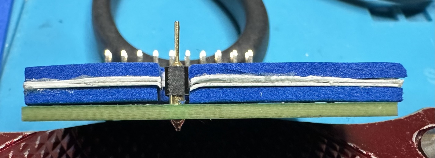
Elsewhere, three layers of the 2mm foam gives support to the rest of the buspirate, and lines up perfectly with the top layer of foam on the PCB. Note that the entire thing is on another layer of foam … else PCB solder joints would change the height.
Next steps
Use of a single unbroken top layer of foam. Basically, I’ll recreate this setup, without the top pieces, and then rubber cement a single piece on top. That single piece will have a border on the sides opposite the debug adapter, so I can then add / build up a “wall” to help align the device onto the pins. Again, using foam means I don’t need to be ultra-precise.
ASCII Art Rulez!
[FOAM]
[FOAM]                 |||
[======FOAM TOP LAYER==|||==========]
[========FOAM====] [FOAM+2xCardStock]          | |
[========FOAM====] [-----PCB------------------------]
[======FOAM BASE LAYER==============================]
Notes on foam & rubber cement
Using EVA foam makes what you’re building very forgiving in terms of dimensional accuracy. It’s stretchy, compressible, and easily worked with. But… adhesives don’t normally work well with this stuff… typically leaving folks frustrated.
However, there’s a trick that allows rubber cement to work well. Before gluing, apply a layer of rubber cement to the EVA foam, and let it dry. Once it’s at least to full tackiness, then you can use rubber cement on it as you would any other material.
I don’t claim to fully understand why this works so well. Yet it does. Thanks to the CosPlay’er who tipped me off to this trick.
Bonus Tip: Apply the rubber cement to both surfaces, and let both dry until tacky before attaching them. Much stronger bond, which is definitely useful for EVA foam.
Second Bonus Tip: If gluing sheets, glue together oversized pieces first, then cut and trim after the rubber cement dries. Trying to align EVA (remember: stretchy & compressible) is a pain, so this way you avoid that pain.
3 Likes
Thank you for the detailed feedback, I’m glad it works on the first try.
The 3P header with the metal slugs was a mistake. It was supposed to be without.
I’m still waiting on mine to arrive, then I’ll put in a revision.
2 Likes