How to FIX your SPI ZIF FLASH PLANK (v3 or less)

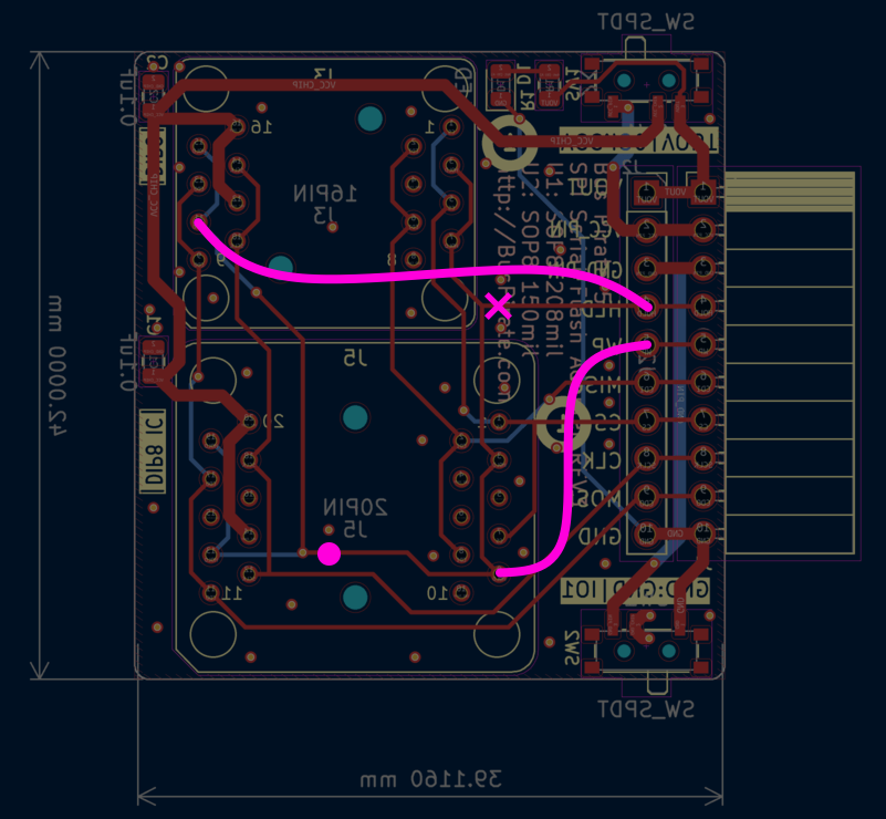
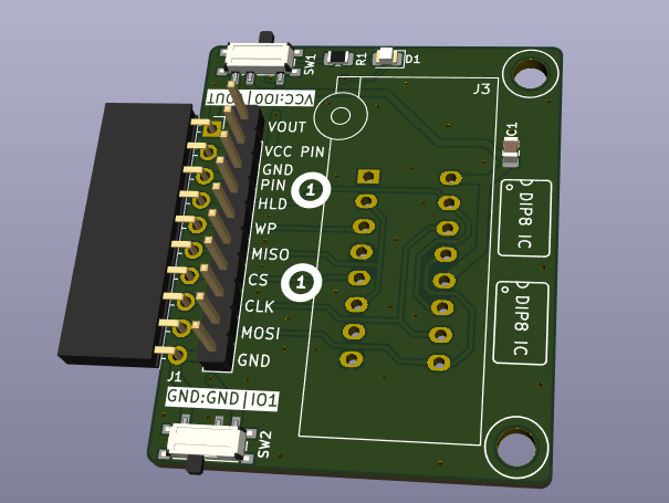
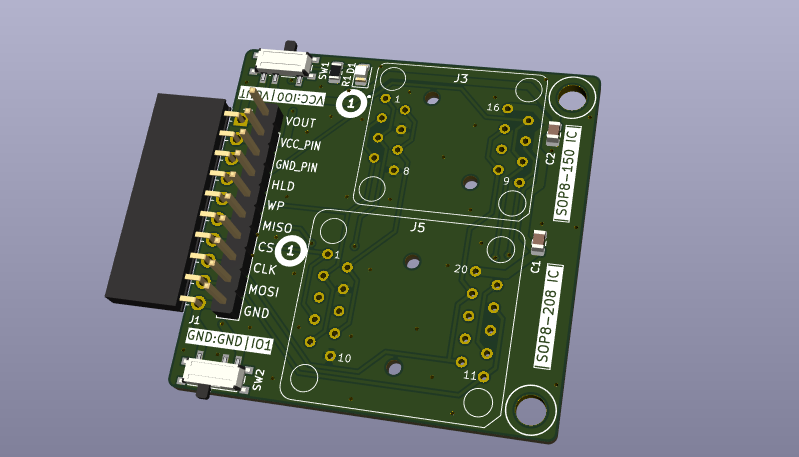
The user @b4shful reports a bug in the routing (2025-05-28) (HOLD BIO is connected to ZIF WP+HOLD, and WP BIO is disconnected from the ZIF).

As a way to procrastinate instead of doing the documentation (@Ian, I’ll try to do it today), here’s a little tutorial:

:police_car_light: First of all: Only do this fix if you’re interested in being able to control WP and HOLD separately; for some users, it might not matter.

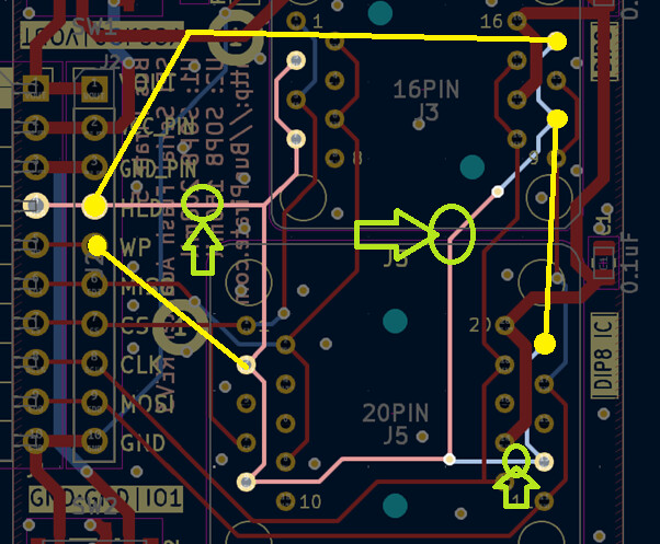
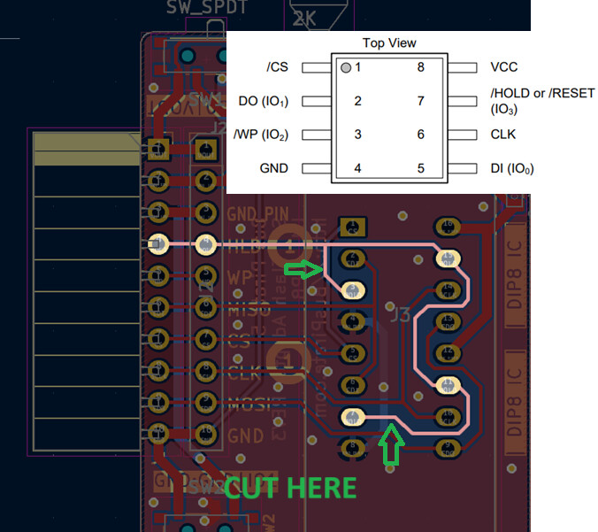
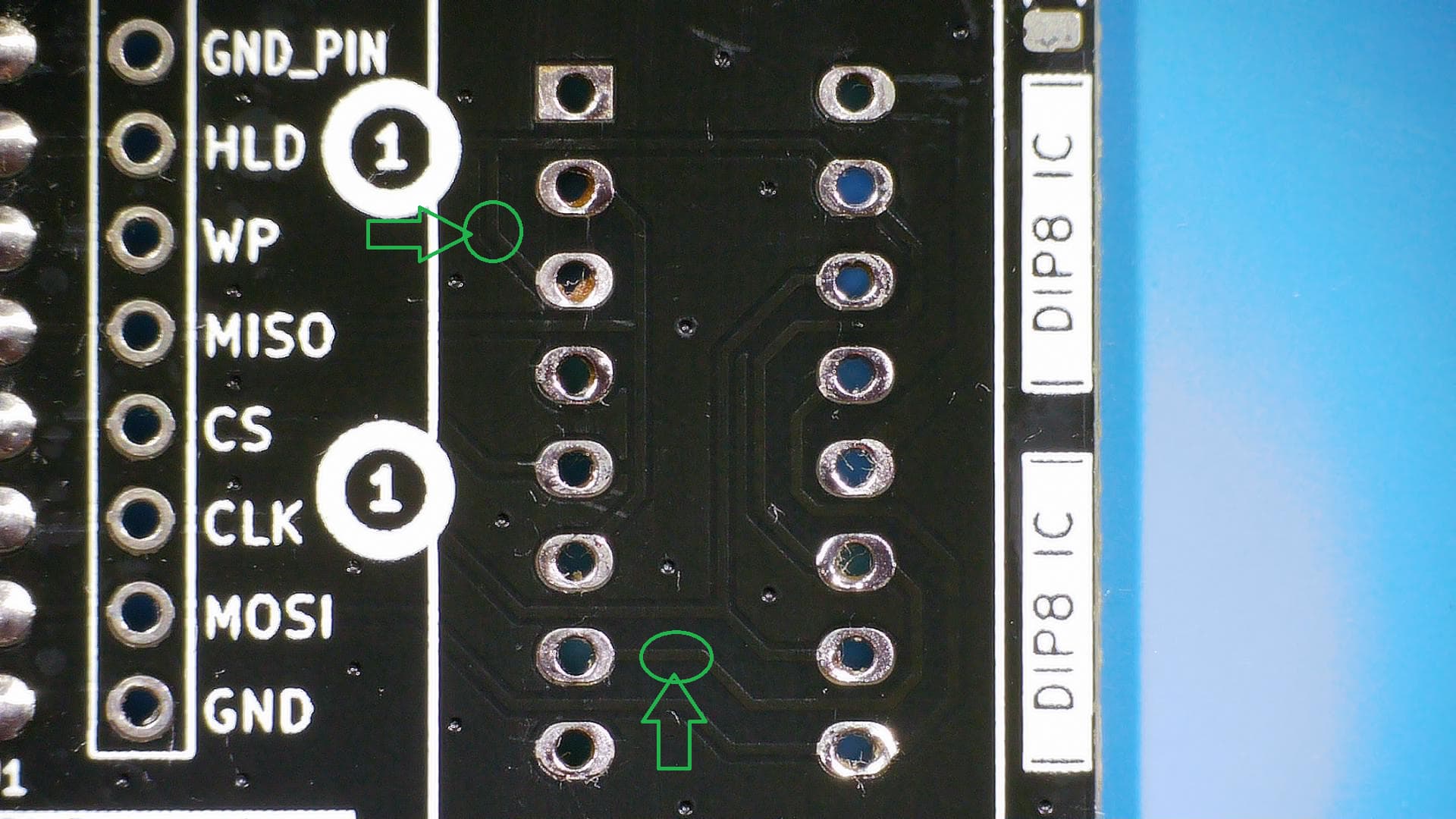
We just need to make two cuts:

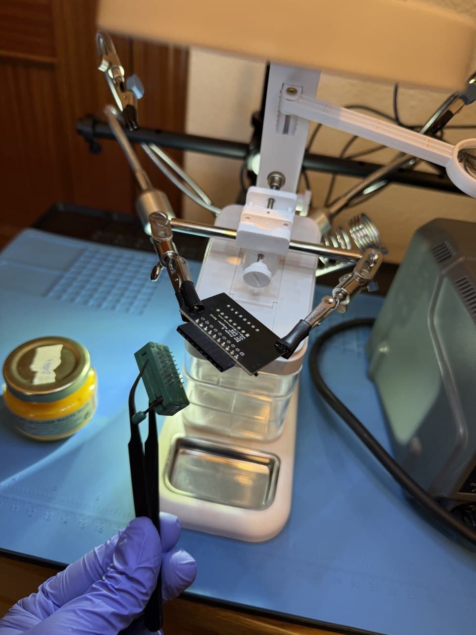
But first, you need to desolder the ZIF socket. Here’s a video “crap-tutorial” by me:

Here are some easy-to-follow steps (I hope):

Add leaded or low-temp solder to each pin.

Add solder paste to the pins:

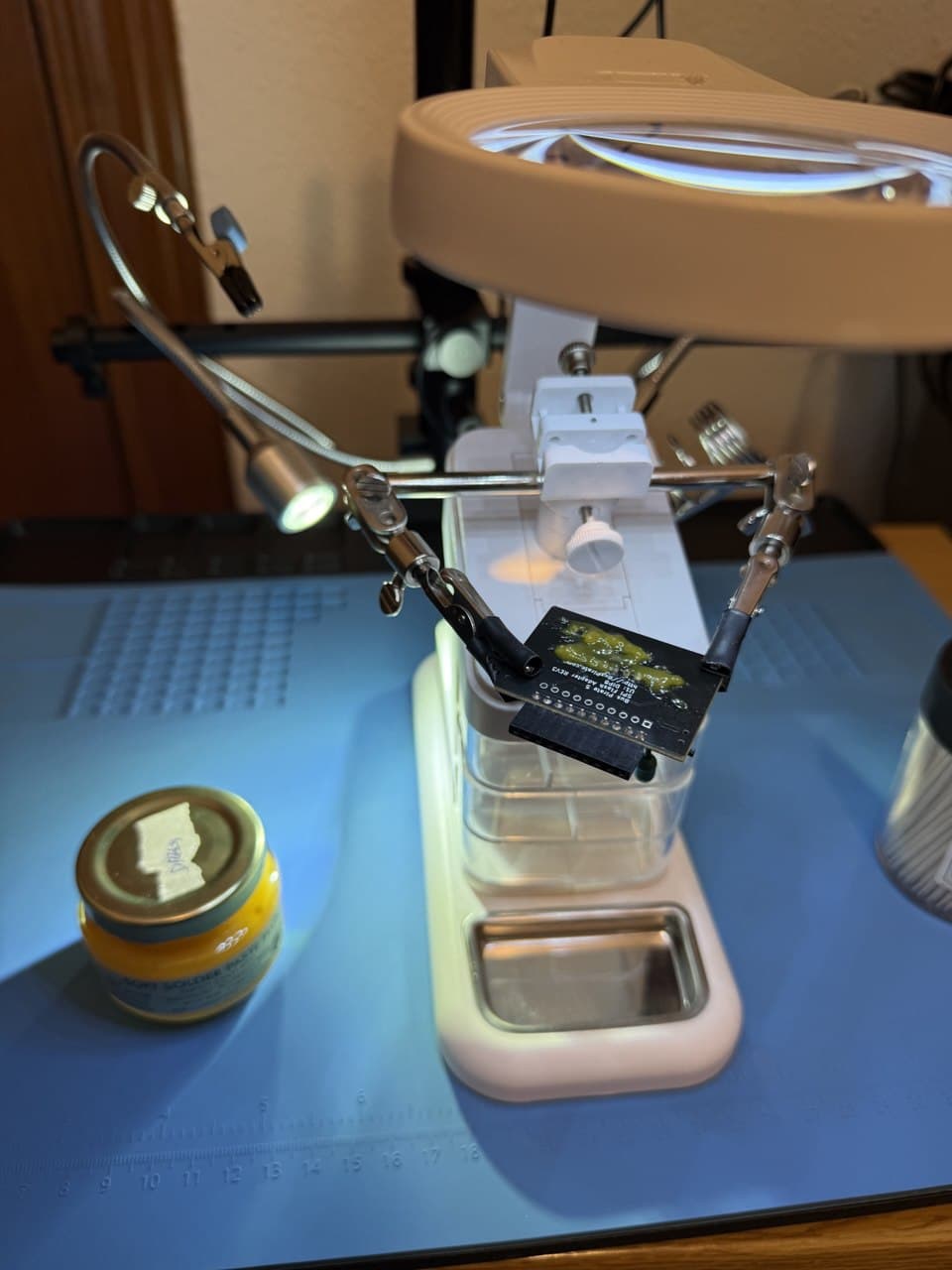
Using tweezers and a hot air gun (I am using 380-400°C), desolder the ZIF socket:

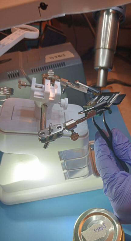
Be patient and don’t pull hard; move the heat gun so that the heat reaches all the pins evenly.

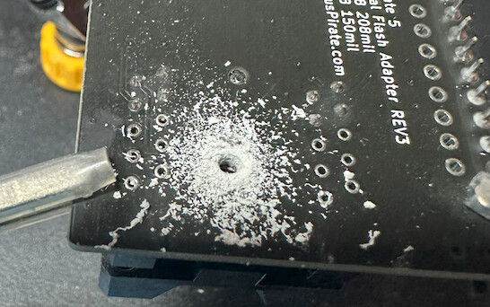
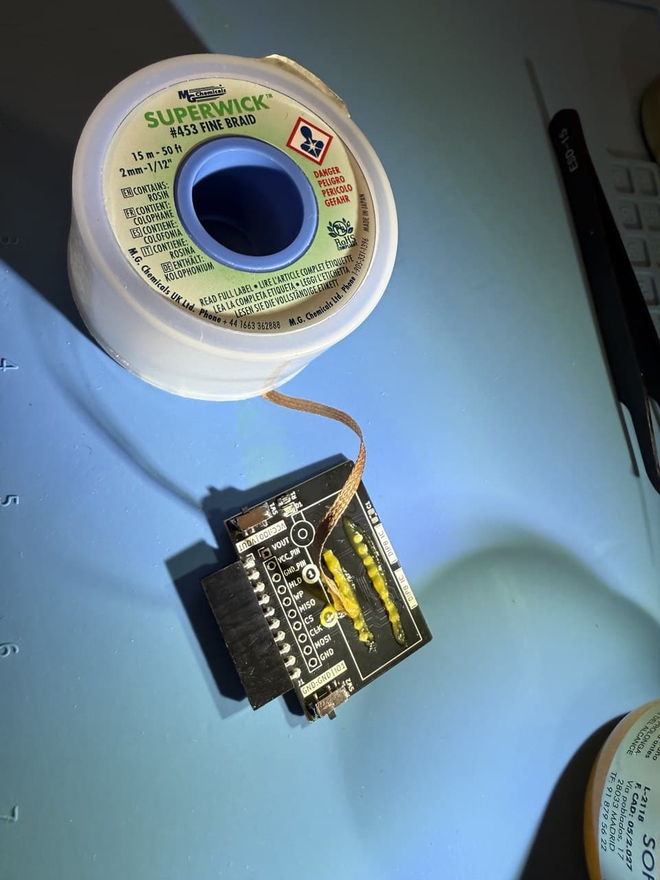
Remove the old solder from the pins using solder wick and flux (You can also use a hot and fine soldering tip—0.5 mm or smaller—and one of those manual solder suckers):
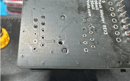
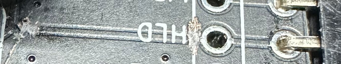
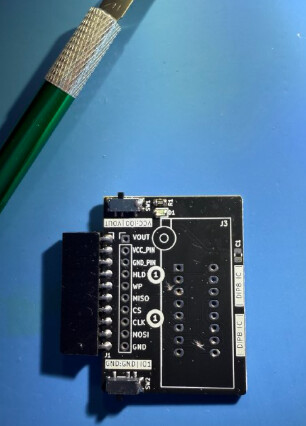
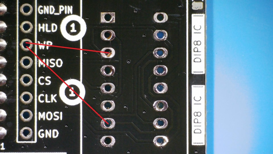
Cut the tracks!

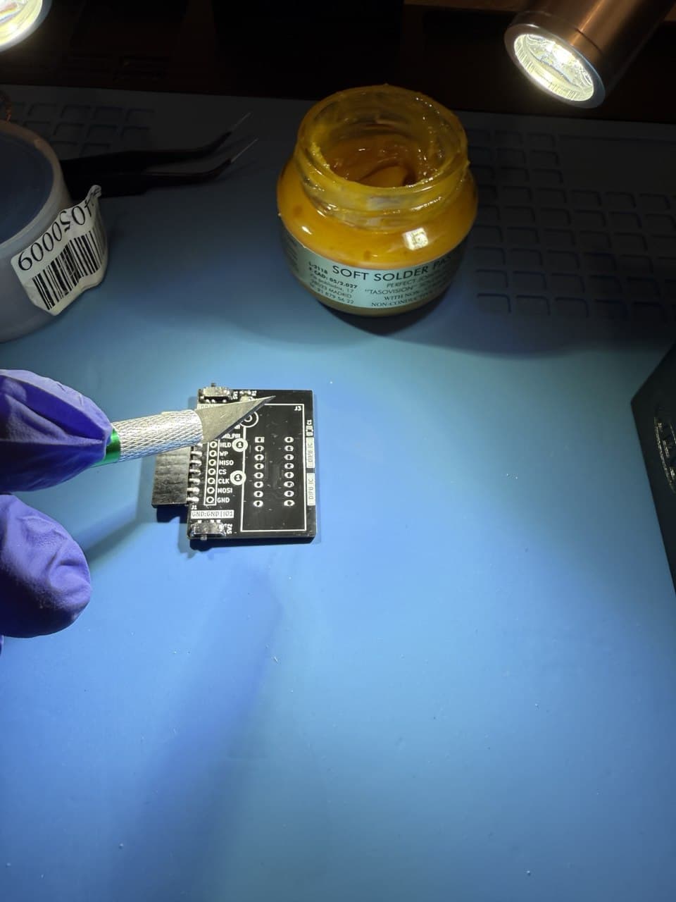
I need to buy new blades; this is slipping and not cutting anything—it’s turned out a bit of a botch job.

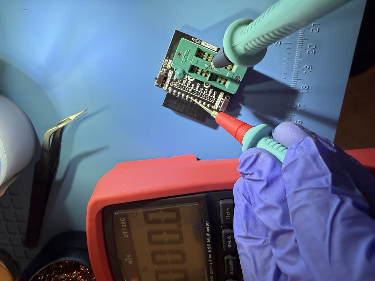
Make sure, using the multimeter in continuity mode, that HOLD and WP are no longer connected to each other.

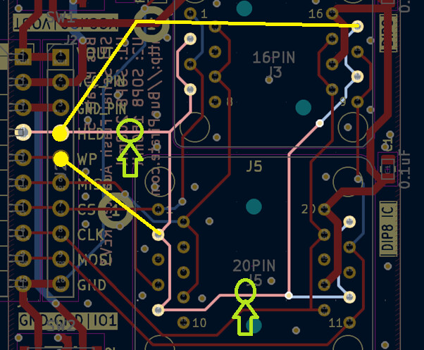
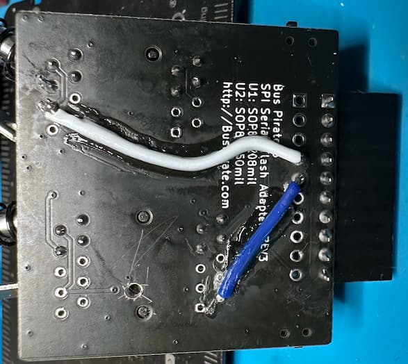
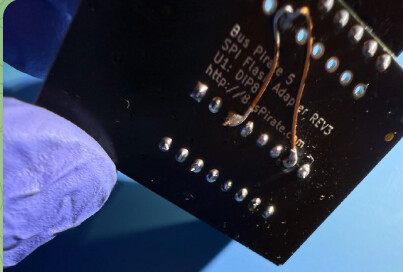
Resolder the ZIF and connect the WP pin to its proper location.

This turned out awful and it’s embarrassing for so many reasons haha, but I’m in a hurry:

Make sure with the multimeter that there’s continuity from the WP BIO pin to the ZIF.

Done!

NOTE: I did it quickly and made it easy for a novice to follow without cutting anything nearby… I didn’t design it with much regard for preserving signal integrity (@electronic_eel hates me for this haha)

3 Likes

Nice work! taking off the ZIFF is a bit extreme, but I don’t see another way to do it.

2 Likes

Nice fix! I wonder how painful and destructive (to the test socket and to the human soul) it would be to fix the SOP8 one :stuck_out_tongue:

To expand on this, in case anyone is less familiar with SPI and might be wondering whether this will matter for them or not, I’ve copied in what I wrote (with some edits for clarity) which might help you decide if you need/want to do the fix:

I ran lots of testing in Single SPI with it connected to an STM32 and it never caused any issues. If I’m correct, in a single chip, single SPI configuration, WP and HOLD being connected to each other will work perfectly as long as both of those pins are active-high or active-low on the chip (usually active low).

So, this issue won’t affect you unless you are:

A) using a chip which for some reason has negation on one of WP/HOLD pins but not the other,

or B) using the adapter to do Quad SPI [I don’t think Bus Pirate 5 firmware has any Quad SPI stuff, so B) would only apply if you’re using it as normal “breakout” adapter connecting to a different board/microcontroller]

Hence for the majority of cases, this bug wouldn’t be noticeable or cause any issues unless B) applies and you are trying to talk to the flash in Quad SPI mode, which turns WP/HOLD into IO2 and IO3 respectively. Theoretically this means that the unfixed adapter board would even be fine with Dual SPI (because that mode only makes DI->IO0 and DO->IO1).

2 Likes

Its easy @b4shful , just follow the same IDEA!


OPTION 1 - Without desoldering

Using a blade between the two sockets

You’ll need to use a very thin blade, and I’m not sure it will fit… also there’s a trace nearby, so be careful not to cut it.

Make sure, using the multimeter in continuity mode, that you’ve cleanly cut all the traces.

So: three wires (yellow line) + three cuts (green circle) (one cut goes in buttom layer)


OPTION 2 - Desoldering only the bottom socket

just 2 cuts (green circle), and 2 cooper wires (yellow line).

I think it would be something like this, right @ian ? I don’t have this plank to test it.

2 Likes

That looks right to me.

1 Like

@ian @b4shful My last image was bad, now its fixed (I hope) and desoldering is only needed in the bottom socket.

2 Likes

Indeed, I would just drill a hole in the board there :slight_smile:

1 Like

I’ve added a method that doesn’t require desoldering anything by inserting the blade between the two sockets.

2 Likes

Another method without desoldering a socket, drilling a single hole instead.

Taking a cue from Ian, I thought about drilling the hole between the two sockets. However, I was pretty sure I’d get the position wrong. :slight_smile:

So, instead, I found a spot I could accurately locate when looking at the bottom of the board:


(note: image reflects back of board)

  1. On back, the two vias right near the drill spot make it easy to locate the drill bit (pink circle).
  2. On front, cut at spot marked with pink “X”.
  3. On the back again, solder two bodge wires between existing unpopulated through-hole pins (easy soldering)
  4. Optionally, super-glue the wires in place

Even I was able to do this! :)

  • Verified existing CLK and HLD signal to socket pins.
  • Drilled the hole
    • Next, I marked the drill position with the tip of a boxcutter blade, and rotated it a bit to puncture the copper layer.
    • Using that guide point, I started a 1/16" drill bit by hand until it was easily self-centering.
    • Moving the drill bit to a dremel, I completed the hole.
  • Verified continuity of the CLK line remained
    • Runs pretty close to drill position
    • If fails, just add another bodge wire … no stress!
  • Verified loss of continuity for the HLD line to left side.
  • Cut the two “X” positions
  • Verified loss of continuity for the HLD line to right side.
  • Verified continuity for four pins on left side
  • Verified continuity for four pins on right side
  • Solder bodge wires into unpopulated socket holes
    • pull insulation away, solder, slide insulation back for tight fit
  • Trim, strip, and solder bodge wires into unpopulated BPIO holes
  • Apply super glue gel (not required if bodge wires are tight)

4 Likes


Updated DIP8 and SOP8 adapters.

  • Fix missing WP
  • Add support feet (finally!)
  • Update revision to REV4
4 Likes

Please let me know when these are available.

1 Like