I have a v5 unit running recent firmware, and I’d like to generate a simple 12MHz square wave on one of the output pins. But, for the life of me I can’t figure out how. I don’t need any communication protocol; just a square wave.
What mode do I use? How do I turn on the frequency generator? How do I adjust the duty cycle?
You’re right! I will add one. That was DIO, but then I went a bit overboard with syncing the pin changes. Now it takes a ton of setup to clear the pins so I can’t send you there anymore.
Setting a pin high or low via the terminal would, unfortunately, not get you to a 12MHz square wave. I presume you’re going to verify with an oscilliscope / logic analyzer.
Is it possible that you could look at the existing modes … maybe one of them has a clock signal that is configurable? Set to the proper clock rate for your use and win. What modes have you looked at with an oscilliscope / LA?
Can you compile the BP5 firmware? If so, add a simple PIO program, modify the firmware to load it, and win!
The frequency generator uses the RP2xxx PWM module and should be able to easily do 12MHz.
Much faster though, and the series protection resistors on the buffers will start to mess things up. It’s a trade off of safety vs speed vs cost. The Bus Pirate is supposed to be inexpensive, mostly rugged to damage, won’t kill your device if you make a mistake while learning, and be relatively fast compared to previous versions.
If you want to spit a 62.5MHz PWM though, that is a different class of device.
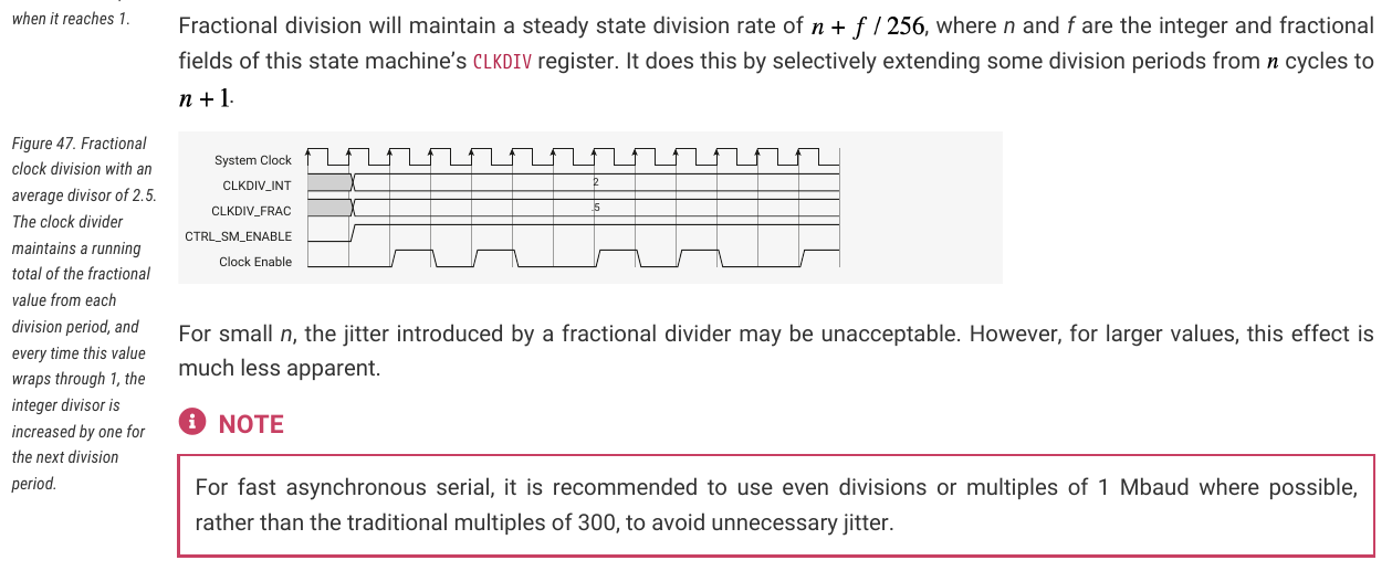
So they don’t have a proper fractional clock divider that creates a new clock signal with some PLL, but just gate the system clock in a non-steady way.
I guess if someone wants exactly 12.88 MHz, most people wouldn’t be satisfied with such a high jitter where just the mean frequency over some time is 12.88 MHz and not each cycle. So I’d say for just this application it wouldn’t be worth re-implementing this with PIO.
A more precise frequency creation would be possible by varying the main sysclock on demand. But this of course comes with it’s own complications, all the peripherals of the BP must still work, stuff like the PWM for the voltage regulator, control timing for the WS2812-LEDs and so on. Not sure if this is worth it either.
Generally increasing the clock to 200 MHz on the BP5 would help getting a better clock accuracy, as the cycles you can choose from get spaced tighter together.
Maybe some future revision of the BusPirate (Version 10 ?) can get a small FPGA that is able to drive the IO and direction signals to the 1T45s and is connected to the RP2350 via SPI or similar. The FPGA would be connected in parallel and activated on demand while the pins on the RP2350 go into HiZ.
This would allow much more complex features than PIO, and would also come with it’s own PLL for the frequency generation case.
Here is a new FPGA that maybe could be a fit, at least price- and space-wise:
Issue could be the number of pins required to the RP2350 and the toolchain. But it looks like there is already some work on the way to integrate these into yosys and nextpnr.
All the possible gatewares would have to be precompiled and put into the flash as blobs. Firmware would then load them on demand.
Oh wow, that is a nice little chip. If it were supported by yosys then it would definitely be a nice thing to include.
The datasheet is pretty skimpy. It says non-volatile, but no mention of t he number of write cycles. Is it possible to load a new bitstream without writing to the internal storage? I always worry about burning out the non volatile storage when making things intended to be changed regularly.
That is why I mentioned BP 10, to give them some time to stabilize it.
I guess you can do that via JTAG. That is a very common feature for FPGAs, because loading the bitstream always means it is internally copied into a string of shift registers. But you are right, this is not explicitly written in the datasheet.
Also they use not regular JTAG, but cJTAG, which multiplexes JTAG over 2 wires. Similar to SWD, but different.
So this is just an idea to keep in mind and wait for the toolchains and docs to improve.
I second this idea. There’s times when you want to do something on the BP that’s not directly related to any one protocol, and it’s somewhat counter-intuitive that you have to pick one just to get access to certain functionality.
For example I often use the BP as a lightweight adjustable power supply, which requires me to pick a mode before I can turn it on.