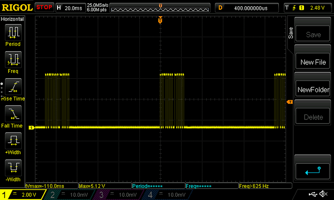
Infrared binary mode (AnalysIR, IRMAN)

I looked through the old IR Toy code and it’s not very complex overall, but it is tightly wound into the PIC registers. Most of the modes are covered elsewhere (SUMP logic analyzer), but two seem worth saving: IRMAN (Lirc, etc), and sampling mode (AnalysIR).

IRMAN

        //final USB packet is:
        //byte 1 bits 7-5 (don't care)
        //byte 1 bits 4-0 (5 address bits)
        //byte 2 bit 7 (don't care)
        //byte 2 bit 6 (RC5x/start bit 2, not inversed)
        //byte 2 bits 5-0 (RC5 6 bit command)
        //byte 3-6 (unused)

A simple six byte packet with decoded RC5 or NEC (etc) shoveled in.

            putc_cdc('O');
            putc_cdc('K');

Response to r or R should be OK.

This is a pretty old protocol and second priority, but it is easy to integrate with the existing PIO IR decoders.

Sampling Mode

This is the mode compatible with AnalysIR software, and perhaps some other random scripts here and there. An IR signal triggers a timer, and we measure the length of each high and low period until a timeout occurs. This one is a real mess because the protocol is dead simple, but is ~~750 lines of configuring registers using hex values. Man the world used to be grim.

I wrote to Chris at AnalysIR, who was instrumental in choosing the right stuff to max out the IR Toy plank, to see what version of the old IR Toy firmware they actually support. He suggested using their AIR syntax instead and I am inclined to do that.

  • $ start character
  • carrier frequency / 1000 (this comes from the learner sensor)
  • ASCII decimals representing the lengths of pulse and no-pulse in uS (anyone think that 90804 is a timeout?). CSV formatted, including the final value
  • Terminated with ;

Since this can be used to transmit, we can add that enhanced feature too.
2 Likes

Pushed IRMAN and AIR support to a new branch irtoy_binmode.

  • IRMAN: just needs a few tweaks to some related code in the rc5 decoder, should be able to test first thing tomorrow.
  • AIR: the framework is there, but I need to write a PIO program to capture the timing of both the demodulator and the learner sensors. Depending on how PIO-y I feel tomorrow this may also get done.
3 Likes

When you are working on IR decoding - are you aware of IRMP?

You can find the documentation here:
https://www.mikrocontroller.net/articles/IRMP_-_english#top

The code of the original version can be found here:

There also is a Arduino library here:

I have used the original version together with ChibiOS in the past and found it quite capable.

2 Likes

Oh, IRMP is GPL 3. This could be an issue.

2 Likes

Indeed I do :slight_smile: I’ve actually messed with getting the code working on 2040. It is another GPL project, so would be a 3rd party port.

However, buoyed by blueTags decision to change licenses for integration I plan to ask if they’d consider as well.

In this case I think using the guts but feeding them PIO data instead of a sampling loop.

3 Likes

All authors must agree to relicensing something.

IRMP is an older project that I think began in 2009. Even though the SVN history just mentions one commiter “ukw”, he merged code submissions from many other authors. All of them would have to agree and I think this isn’t feasible.

3 Likes

Good point. Too bad. I stand by my open licensing approach.

4 Likes

IRMAN mode is working, but I ran into some usability issues that I need to clean up:

  • Power supply needs to be enabled for the plank
  • Bad things happen if in an existing mode in the terminal, binmode needs to reset the terminal mode in some cases
  • Use button press to exit a locked terminal binmode
.define public COUNTER_INPUT 21
.define public COUNTER_GATE_PIN  22

.program counter_gate
.side_set 2 opt
    wait 1 gpio COUNTER_INPUT                   
    wait 0 gpio COUNTER_INPUT   side 0b01
    wait 1 gpio COUNTER_INPUT              
    wait 0 gpio COUNTER_INPUT   side 0b10

.program counter
    pull noblock
    mov x, osr
    mov y, x
wait_for_gate:
    jmp pin wait_for_gate       
counter_loop:
    jmp pin data_push
    jmp y-- counter_loop
data_push:  
    mov isr, y
    push noblock

Source.

For AnalysIR support we need to record the length of each IR pulse. As far as i know the RP2040 doesn’t have a CCP module that can gate a timer like the old PICs did. PIO should be a good alternative.

The above two programs are from the RPi forum. One follows the signal, the other counts down from a preloaded value that also serves as a timeout. I get the elegance of gating the timer, but I don’t know why a slightly longer single program wouldn’t work as well.

The other thing: this approach uses a GPIO pin to communicate between the to PIO programs. GusmanB also uses this approach. There is something funky about the PIO that makes communicating between them weird, but I don’t remember at the moment. There are in fact IRQs between the PIOs and they are able to set, clear, and wait on them. I guess I’ll remember when I write the program.

1 Like
.program ir_in_counter
    pull
    mov x, osr
    mov y, x
wait_for_high:
    jmp pin low_high
    jmp y-- wait_for_high
low_high:
    mov isr, y
    push noblock
    mov y, x
wait_for_low:
    jmp pin wait_for_low
    jmp y-- wait_for_low
high_low:
    mov isr, y
    push noblock
    mov y, x   
    jmp wait_for_high 

Ah yes, the “can only jmp on pin high limitation”. The logic of wait_for_low has all kinds of issues. I’m sure there’s a very smart trick to get it going, but I have to think about it a little more.

I see why the above example uses two copies of the program to get high and low pulse time. Ugh.

1 Like

I think I have a solution!

.program ir_in_low_counter
    pull side 0b1       ;pull counter reset value, stall other counter
    mov x, osr          ;save counter value in x
.wrap_target
reset:
    wait 0 pin 0 side 0b0       ;stall and wait for IR mark (low from demodulator)
    mov y, x side 0b1   ;side set pin to high, other counter stalls
wait_for_high:
    jmp pin low_high    ;pin goes high, stop counting, push count
    jmp y-- wait_for_high   ;loop until counter hits 0
low_high:
    mov isr, y side 0b0 ;get timer value, enable other counter
    push noblock
.wrap

First program measures LOW (mark) periods from the IR demodulator with a timeout.

  • Uses a free pin as a side set pin to communicate with a second PIO state machine (remember to make the buffer an output!)
  • Waits for the pin to go low, disables the second PIO state machine, and starts counting the period of low with a timeout
  • Either pin goes high or timeout: push the counter value and enable the HIGH counting state machine via side set pin

.program ir_in_high_counter
    pull                ;pull counter reset value
    mov x, osr          ;save counter value in x
.wrap_target
reset:
    wait 0 pin 0        ;stall and wait for side set pin in low counter
    mov y, x            ;reload counter
wait_for_high:
    jmp pin low_high    ;pin goes high, stop counting, push count
    jmp y-- wait_for_high   ;loop until counter hits 0
low_high:
    mov isr, y          ;get timer value
    push noblock
.wrap

This program measures the HIGH (no mark) signal time. Basically the same program, but instead of waiting for HIGH on the demodulator pin, it is waiting for the inverted signal on the side set pin from the first program.

Possible glitches

  • No way to stop the temporary enabling of the HIGH counter when LOW times out. It’s probably possible, but not done here.
  • HIGH (normal state) will produce a continuous stream of 0 samples. This will need to be sorted in firmware.

EDIT:

.program ir_in_low_counter
    pull side 0b1       ;pull counter reset value, stall other counter
    mov x, osr          ;save counter value in x
    wait 1 pin 0        ;stall until the pin initially goes high
.wrap_target
reset:
    wait 0 pin 0        ;stall and wait for IR mark (low from demodulator)
    mov y, x side 0b1   ;side set pin to high, other counter stalls
wait_for_high:
    jmp pin low_high    ;pin goes high, stop counting, push count
    jmp y-- wait_for_high   ;loop until counter hits 0
    jmp counter_push    ;skip the side set, do not enable the other counter    
low_high:
    nop side 0b0        ;side set to 0, enable other counter only if not timeout    
counter_push:
    mov isr, y          ;get timer value
    push noblock
.wrap


.program ir_in_high_counter
    pull                ;pull counter reset value
    mov x, osr          ;save counter value in x
.wrap_target
reset:
    wait 0 pin 0        ;stall and wait for side set pin in low counter
    mov y, x            ;reload counter
wait_for_high:
    jmp pin low_high    ;pin goes high, stop counting, push count
    jmp y-- wait_for_high   ;loop until counter hits 0
low_high:
    mov isr, y          ;get timer value, enable other counter
    push noblock
.wrap

Update to the LOW program.

  • Stall until a high signal is observed (eg a IR plank is plugged in)
  • Only enable the high counter if we saw an actual transition from low to high
3 Likes

Getting close!

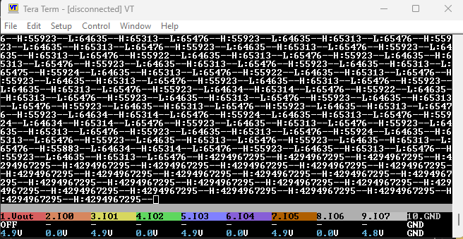
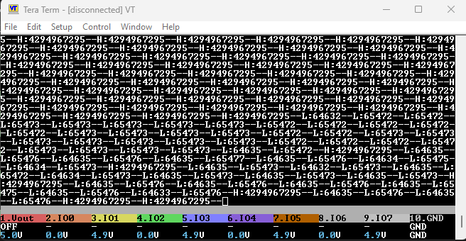
This shows the raw count (down) values. H (high) counter is rolling back from 0x00 to 0xffffffff. L (low/mark) counter is returning 0xffff-time_of_mark.

The low timer should be disabling the high timer through the side set pin, but the pin is stuck at ground. So, the high timer just runs constantly because sideset is low, but the low timer does just measure the low periods correctly.

Something about that side set pin is not side-setting… I’m sure it will come to me first thing tomorrow.

Current work pushed to the IR Toy branch.

2 Likes

If you want to debug the PIO behavior, checkout the following:

Using that project as a base, it should be fairly easy to change it to use your own PIO code, and then you can step through what is otherwise has hard-real-time requirements (due to the IR sender & receiver).

4 Likes

Side set pin is now side setting, but only when the HIGH PIO program is disabled. Getting close to figuring this out.

2 Likes

    // pin to input to PIO
    //pio_sm_set_consecutive_pindirs(pio, sm, pin_pio2pio, 1, false); //input

It was this configuration step in the HIGH program. It changes the pin direction for the whole PIO instead of just the current state machine. Now to tweak the timings :slight_smile:

2 Likes

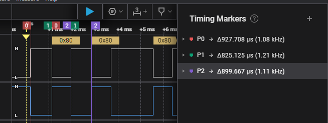
H:65492–L:927–H:825–L:899–H:850–L:1840–H:823–L:925–H:825–L:924–H:825–L:923–H:826–L:923–H:1661–L:1838–H:827–L:924–H:825–L:922–H:827–L:925–H:824–L:923

Wow, even better than I hoped.

927~=927.7us
825~=825.125us
899~=899.667us

Todo:

  • Sample the learner sensor for the modulation frequency
  • RAW option in infrared mode that displays/sends AIR format data
  • Commands to save and replay IR signals
  • binmode to receive/send AIR format data
3 Likes

You wrote in chat:

Accurate frequency measurement on the Pi Pico RP2040 using C – Lean2 This is nice using DMA, but I would also need to tie it to a pin interrupt I imagine to get the right response time. The PIO method just looks easier and easier.

I never realized the rp2040 PWM peripheral could be used for frequency measurement… TIL…

Of course, there are a few limitations. The PWM peripheral can only measure on odd pin numbers (must use channel B). Also, it can only measure either the rising edge, or the falling edge … not both.

Maybe it’s good enough, but … so many time I wish things could just be configured to fire on either edge. [sigh]

1 Like

I don’t quite know the right term, but it’s like the GD (Goodwin) stm32 clones. Close, but not one to one. Once you get in there you find gremlins.

The RP PWM “slices” are really ancient even compared to old PIC stuff. The old 24f in the BP v3.x had a bare bones CCP module (capture, compare, PWM), it could gate a timer and do various measurement of ticks, full cycles, etc.

The RP doesn’t have any of that, and the alternate is abusing way more advanced peripherals (DMA, PIO).

3 Likes

Minimally acceptable silicon?

When I lived in China and ate at street food places they would bring a plastic cup for one’s beverage. If the cups were any thinner they’d be plastic bags without structure. They weren’t great cups, just the minimal acceptable amount of plastic to make a cup shape.

RP chips make me think of this.

4 Likes

I recall something odd with PIO programs, but now I cannot find the original source (I believe it was a github issue report, likely about a complex many-pin high-speed interface driven by multiple PIO state machines).


Very hard Trivia Question

Could there be unexpected behavior when side_set is used?

To the best of my recollection, the program in question was complex, with multiple PIO state machines synchronizing, and having very specific timing requirements, to drive a multi-GPIO output with very precise timings … so some GPIO were toggled by both state machines.

The problem was, sometimes the bus output was corrupted … but noone could find a logic problem with the synchronization …

IIRC, the instruction at issue was something along the lines of:
wait 1 IRQ 1 side 1;

How could something that simple be hard to understand?

Hint #1:

The problem was that the other state machine’s attempts to set a GPIO (the same one being side-set above) low were being ignored … and thus the GPIO stayed high when it shouldn’t.

Hint #1:

When do you think that the side-set GPIO in that instruction should be set to 1?

Root Cause?

The author expected the side-set GPIO to be set when the program jumped to this instruction (and it was), and then to wait for the IRQ to occur (which it did).

The unexpected thing was that the side-set GPIO was also set during every clock cycle the state machine was waiting for the IRQ, essentially overwriting other changes to the GPIO made elsewhere.


Does the SDK really say that's expected?

Maybe…

The SDK says the side_set_value:

Is a value […] to apply to the side_set pins at the start of the instruction.

The SDK says the delay_value:

Specifies the number of cycles to delay after the instruction completes.

Thus, an instruction execution has three phases:

  1. side_set_value
  2. instruction itself, after the side_set (priority from the instruction in case of conflicting changes)
  3. delay cycles, after the instruction completes

What the SDK says about Stalling:

State machines may momentarily pause execution for a number of reasons … the program counter does not advance, and the state machine will continue executing this instruction on the next cycle.

If you read “will continue executing” as being identical to restarting execution at that same address, then maybe this is normal.

So, if the instruction is stalled, it will “continue executing” on the next clock cycle. But … “continue executing” should really say “restart execution”, because the side_set_value occurs as well on that next clock cycle, not just the instruction.


Bonus Question #1

When the program was originally written and tested, the same programs were used without failures. The only difference was the order in which the programs were loaded (and thus which state machines were used).

Why might this be (documented reasons only)?

Hint #1 … thought experiment

Consider the following two minimal PIO programs:

.program blink
    set 1 gpio 5
    set 0 gpio 5
.program solid
    set 1  gpio 5

Load blink into SM zero, and solid onto SM one. What do you expect the output of GPIO5 to look like?

Now load blink into SM one, and solid onto SM one. What do you expect the output of GPIO5 to be now?

Hint #2 … sdk reference.

See rp2040 datasheet section 3.2.5, “Pin Mapping”.

Solution:

Section 3.2.5, “Pin Mapping” states:

For each individual GPIO output (level and direction separately), PIO considers all 8 writes that may have occurred on that cycle, and applies the write from the highest-numbered state machine.

Thus, although both state machines were writing to the same GPIO, when there was a conflict, the result from the higher-numbered state machine won. The programs in question happened to work correctly originally because the priority changed, and therefore what happened when both programs wrote to the same GPIO changed.


Fun, eh?

Simpler (?) Bonus Question #2

How can you correctly decrement the X register in a single instruction?

Answer:

The following is a requested new pseudoinstruction:

    jmp (x--), <uniquelabel>
<uniquelabel>:

Note that the unique label immediately following the jmp is required,
but there is an edge case…

When this is the last instruction in the program, the <uniquelabel> must be placed at the target_wrap location (or start of program).

I’ve been hoping they add this pseudo-instruction for more than a year…


2 Likes

As far as I’m aware you can only deincrement X or Y on a jmp

2 Likes