Infrared binary mode (AnalysIR, IRMAN)

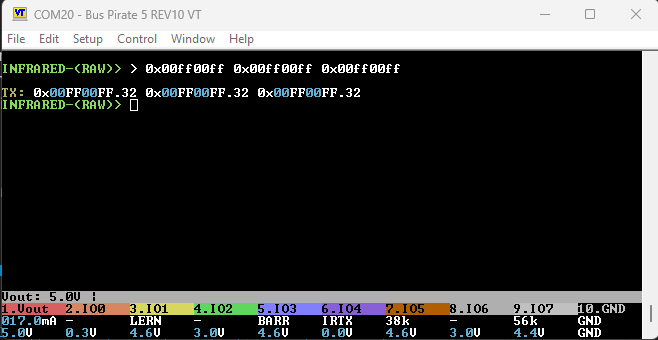
Measuring frequency from a remote control is a really nasty issue on the RP2xxx. The above code does work, for some protocols.

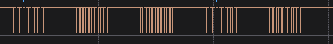
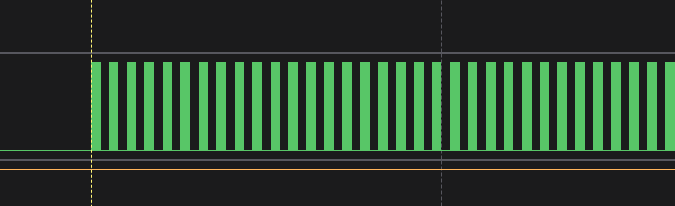
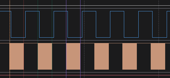
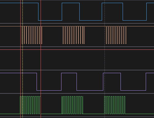
The problem: all of these methods work fairly well for a constant frequency, but the IR remove control uses bursts of pulses. Without a hardware method to trigger the pulse counter, we are at the mercy of interrupt latency to catch the pulse at the right place.

    if(!gpio_get(bio2bufiopin[BIO1])){
        freq_counter_start();
        while (!freq_counter_value_ready());
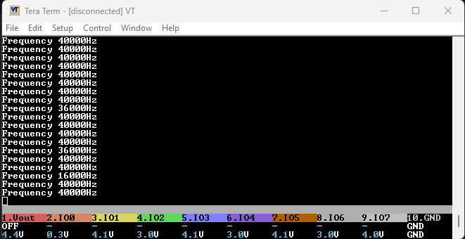
        printf("Frequency %uHz\r\n", edge_counter_frequency());
        //gpio_set_irq_enabled_with_callback(bio2bufiopin[BIO1], GPIO_IRQ_EDGE_FALL, true, &gpio_fall_irq_handler);
    }

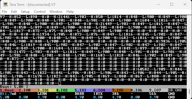
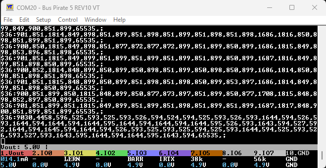
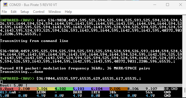
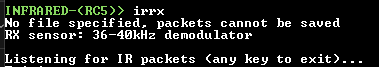
I’m using a tight loop for testing, and you can see above we get 40khz when we should get around 36khz. If this was triggered on interrupt it would get even dodgier.

After some study, I have an idea that may not pan out:

  • A PIO program that waits for pin to 0, then pushes a work into the PIO FIFO
  • The PIO FIFO can create a dreq (data request) over DMA
  • A PWM is used as a gating timer, which down counts our sample interval when the PIO FIFO dreq fires
  • One B slice is the pulse counter, which counts until the gating timer times out and fires a DREQ.

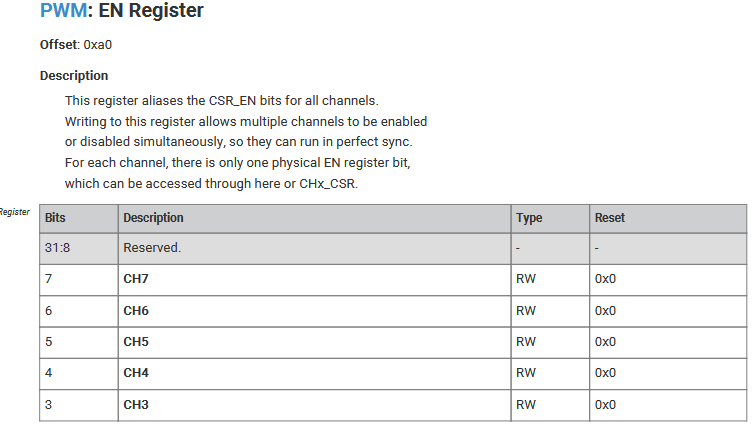
The unknown: is it possible to do pwm_set_mask_enabled((1 << counter_slice) | (1 << gate_slice)); with a single register write with DMA? It looks like yes, it is a single register write.

Another possibility is to use the DMA pacing timer to control the pulse count timer, I believe?

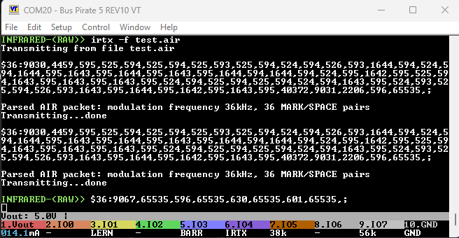
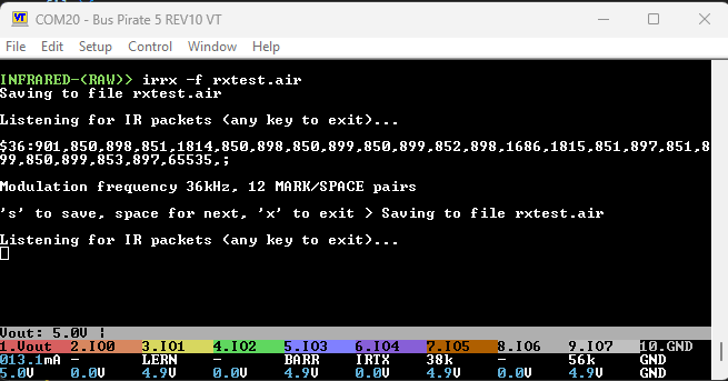
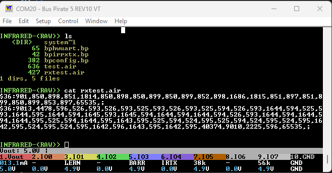
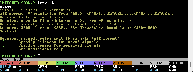
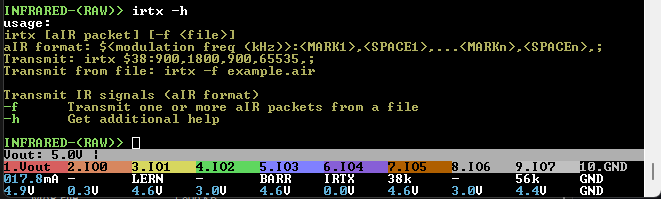
I’m going to let the frequency bit set for a while and finish building out the raw and AnalysIR RX/TX stuff.

3 Likes

Added a RAW sub-protocol to INFRARED mode. Currently it just spits out the raw timings. It does delay for a valid falling edge before starting, but after that the measurements never stop.

Next I’ll get it output the data in AIR formatted data packets, and then on to transmitting AIR formatted data packets.

Anyone with DMA experience think the frequency measuring approach is workable? That’s the only part I’m still concerned about.

2 Likes

Updated with answer. :slight_smile:

1 Like

I see a bunch of H:0 output … is that intentional? Does that mean UINT16_MAX?

For frequency, is there any reason not to use PIO to measure it?

1 Like

Yes, there is a halt until a valid falling edge, but after that it reports times continually. It should be -1 I guess, the 0 means 0xffff duration high.

For the PIO I see two ways without any extra hardware. One is to duplicate the current timing program on two more state machines and an extra pin, and do a running measure. Figuring out when to trust the data in firmware will be a bit dicey.

The other is to set it up as a 0.5us logic analyzer triggered by falling edge and shuffle bits to figure out the duration.

I’m sure there’s a proper way I just don’t have a grasp of, but these are the options I see.

2 Likes

Then again… with the rising and falling edges already known, isn’t that enough for post-processing to determine the carrier frequency?

Maybe I’m missing something important?

2 Likes

The issue I see is when and how to trigger that. If we do wait 0 pin 0 then it stalls and we can’t increment (or deincrement). I probably just don’t know the right design patterns in ASM, but I also can’t find any examples that work like a proper CCP module.

1 Like

AIR (AnalysIR) formatted data packets. RC5 (top) and NEC (bottom). Frequency faked.

$36:900,850,1815,849,898,851,877,872,877,872,899,851,899,850,899,1686,1815,849,898,853,896,851,898,65535,;

  • $ - Start AIR packet
  • 36 - Modulation frequency in kHz
  • : - Start of IR pulse timing data (in us), beginning with MARK (IR pulse)
  • 900 - Length of first IR MARK/pulse (in us)
  • , - Each value separated by a comma, including after the final timeout
  • 850 - Length of first IR SPACE/no pulse (in us)
  • , - Each value separated by a comma, including after the final timeout
  • … More MARK/SPACE timing pairs
  • 65535 - Final timeout, when no IR MARK has been sensed in 65535us
  • , - Remember the comma after the final timing
  • ; - Terminated with a semicolon

If you have AnalysIR, you could now go into INFRARED mode, enable power, and probably capture the packets. There will be a dedicated binmode for this, but the format is the same so it will probably work.

2 Likes
.program ir_out
.side_set 1 opt pindirs
.wrap_target 
public entry_point:
    out x, 16 side 0b1  ;pulse duration
mark:
    jmp x-- mark        ;loop until counter hits 0 
    out x, 16 side 0b0  ;pulse interval
space:
    jmp x-- space       ;loop until counter hits 0
.wrap

Mercifully the transmit PIO program should be pretty easy.

  • Setup PWM for desired frequency
  • PIO program then manipulates the pindirection (in/out) to time the MARK and SPACE periods.

I think it would be extra clever to use the FIFO in 32 bit mode, and pack one MARK and one SPACE in every write. That would prevent the IR Transmitter from ever being stuck in the “on” position (especially important at higher current levels).

2 Likes

Slight change of plan. The GPIO output can only be assigned to one peripheral, so we get either PWM or PIO but not both. I was hoping to save a statemachine by using the PWW hardware and just flipping the pin direction with the PIO, but that doesn’t seem possible.

.program ir_out_carrier
.wrap_target
public entry_point:
    set pins, 1 
    set pins, 0
.wrap

Instead I used a second tiny PIO program to do the PWM. It works, you can see the gating of the signal in the trace above.

.program ir_out_carrier
high:
    set pins, 1 [2] ; set the pin high (2 cycle) 
.wrap_target
public entry_point:
    set pins, 0     ; set the pin low (1 + 1 cycles)
    jmp pin high     ; only high if pin is high
.wrap

I’m not totally happy with this because it leaves the constant current driver almost floating instead of at a hard ground. Using one of the free pins as a jmp pin, I think this is a better arrangement.

1 Like

The good news is we’re able to receive and transmit IR packets now :partying_face:

.program ir_out
.side_set 1
.wrap_target 
public entry_point:
    set pindirs, 1 side 0b0 ;set pin to output
    out x, 16 side 0b0      ;pulse duration
mark:
    jmp x-- mark side 0b1   ;loop until counter hits 0 
    set pindirs, 0 side 0b1 ;set pin to input
    out x, 16    side 0b1   ;space duration
space:
    jmp x-- space side 0b0  ;loop until counter hits 0
.wrap

.program ir_out_carrier
high:
    set pins, 1 [2] ; set the pin high (2 cycle) 
.wrap_target
public entry_point:
    set pins, 0     ; set the pin low (1 + 1 cycles)
    jmp pin high     ; only high if pin is high
.wrap

The timing isn’t quite up to my standard though. I’m going to try a hybrid approach that 1. Enables the PWM via a shared pin so that it always starts. I’m not sure this will really be better… there is still the opportunity to start up to 2 cycles late, and at least 1.

It seems the only totally reproducible way to handle this is convert the us measurements into ticks based on the current modulation frequency and count those out directly in the PWM. Given that we could get workable output from a PIC going 12MIPs in a timed loop, I’m not sure it’s THAT critical.

Next

  • irrx irtx commands to record and replay remote codes (both to file, and from a string)
  • Cleanup AIR binmode for AnalysIR
  • Grrrrr - finding the carrier frequency

Almost done and ready to merge into main.

4 Likes

irtx is used to transmit AIR formatted IR signal timing packets from the command line or a file.

One or more AIR packets can be sent from a file using the -f flag. Each packet should be on a line terminated by \n.

This is nearly ready to be merged into main for beta testing, but there are some rough areas to address:

  1. RX should be disabled during TX to avoid garbage data. Both cannot function at the same time (without heavy modification) because both depend on a tight timing loop to keep synchronized to data.
  2. irtx and irrx should only be available in the RAW protocol of INFRARED mode, or crashes are bound to happen. There is currently no way for a command to detect the active sub protocol.
  3. Help, when functionality is complete.
3 Likes

Some IR signals are easier to decode than others. Lego Power Functions (LPF) are apparently one of the more difficult ones.

I’ve included an AnalysIR history file showing multiple LPF captures.
In the ZIP file are some AnalysIR history files capturing various IR signals:

  • Lego Power Functions IR Remote 8885 (lego) (amazon)
  • Laser tag set used DISNEY IR protocol
  • Set of random LED candles from 2021, NEC protocol
  • A TrippLite HDMI switch using NEC protocol
  • A USB switch, also using NEC protocol

Various_IR_Signals.zip (215.4 KB)

Lego Power Functions IR 8885

For the LPF history, the signals are named as follows:
[x]###-cccc-dddd

  • x prefix indicates signal failed (at that time) to be detected as LPF
  • ### is a channel, selected from { CH1, CH2, CH3, CH4 }
  • cccc is a color, selected from { Blue, Red }
  • dddd is a direction, selected from { up, down }

Chris figured out how to decode the Lego Power Functions IR signals:

Also, this will be a very difficult protocol to receive correctly with most IR receivers …
I’m curious… how did you know the difficulty this would cause IR receivers?
Most IR receivers are rated to get the timings accurate to +/- 6 carrier cycles. This equates exactly to the actual mark time of this signal (158 uSec). Thus it is essentially a badly designed signal for use with standard receivers.

Note the important bit:
IR receivers commonly will be off by +/- 6 carrier cycles

If you want to decode the Lego Power Functions in AnalysIR, here’s the custom settings. Not sure, but you may also need to request the “dev” version of AnalysIR ( at time of posting, this was 1.19.200.9446).

[CUSTOM56]
altName=LEGOPOWER
Generic=True
Syntax=HB016T
Marks=158,158,158,158,0,0,0,0
Spaces=553,263,1026,0,0,0,0,0
Header=158
HeaderSpace=1026
Mark=158
Space0=263
Space1=553
Delta=100
Bits=16
Carrier=38000

Because of choices made in the LPF protocol (varies time between  signals, based on which channel is selected), it made capturing ~2 seconds of continuous signal the approximate limit with existing hardware at that time, so that in 2016, he said:

However, no device I am aware of can continuously record an IR signal.

Challenge: Can the BusPirate record (and send over USB) a continuous recording of IR signal? (e.g., >20 seconds?)

I’m going to have to find the LPF transmitter, and find out. :slight_smile:

2 Likes

Very interesting. The hardware limitation makes sense.

1 Like

irrx captures infrared remote control signals as a sequence of on (MARK) and off (SPACE) times in the AIR (AnalysIR) format. A capture can be saved to a file.

I’ve captured two different types of remote control codes (RC5, NEC).

irtx replays the recorded sequences.

1 Like

I’m ready to get this cleaned up, but I’m not sure the best way to proceed.

I like having RAW mode, but the only difference between RAW mode and the irtx/irrx commands is that the timing sequences stream in constantly. irrx could also be modified to have this behavior.

It matters because we either need to:

  1. Make the irrx and irtx commands aware of the sub-mode and only operate in raw mode, or
  2. Temporarily tear down the current mode to run the RX/TX programs.

I think #2 is the most user friendly option, but then there is really no point in having a separate RAW mode because all modes support the commands.

RAW does have the async receive function, which is nice I guess, but transmit is not really usable in the current state.

Any thoughts?

2 Likes

Specific protocols (NEC/RC5) have a modulation frequency determined by the PIO program/protocol specs. The correct frequency is now auto-selected. This simplifies setup, but actually just removes an un-honored selection from setup process.

irrx and irtx now work normally regardless of the current mode. This is done by tearing down the existing PIO stuff and then reinstalling it when the program exits. It is still buggy during the switch over.

image
irrx updates:

  • -s flag selects the demodulator used (38B, 38D, 56D), 38D is the default (and most common)
  • t re-transmits the just-captured packet

Accomplished:

  • Full rework of the base irio_pio driver
  • irrx and irtx complete, and working regardless of mode (bugs)
  • irrx added re-transmit option, and configuration flag to choose the demodulator used
  • Minor rework in the infrared mode to make things a bit less scattered
  • Protocol modes now use the correct default TX modulation for the selected protocol
  • The number of bits transmitted/received is automatically set per sub protocol (RC5, NEC = 16bits, RAW = 32bits).
  • TV-B-gone command added to play 100+ TV off codes ( Mitch Altman’s OG hacker project, also developed into a kit by Adafruit)

TODO:

  • Fix occasional freezes when swapping/resuming different PIO programs
  • Reorganize the way TX happens in response to syntax to work in RAW mode
  • Update AIR binary interface to use the new get_frame function in irio_pio
  • Help menus and usage examples
  • Get modulation frequency (grrrrr)

Everything but the modulation frequency can probably be finished tomorrow and then merged into main for a preview release.

1 Like

This is about as good as it is going to get given the limitations of the PIO.

Infrared RAW mode writes are 32 bit frames.

  • The high 16 bits are the number of microseconds to enable the IR transmitter
  • The low 16 bits are the number of microseconds to disable the IR transmitter

I don’t recommend building signals this way. Use the irtx/irrx programs and the AIR packet format instead, but it is working. Receive is disabled while transmitting because of the structure of the PIO program.

TODO:

  • Fix occasional freezes when swapping/resuming different PIO programs~
  • Reorganize the way TX happens in response to syntax to work in RAW mode
  • Help menus and usage examples
  • Update AIR binary interface to use the new get_frame function in irio_pio
  • Get modulation frequency (grrrrr)

Freezes during PIO program swaps were happening because the RC5 deinit function only removed one of the two PIO programs used.

Bugs

irrx and irtx now run in all subprotocols (RAW, RC5, NEC) by tearing down the current subprotocol PIO programs, loading the RAW PIO programs, and then restoring the subprotocol PIO programs on exit.

However after using irrx or irtx, neither RC5 or NEC subprotocol is able to transmit. Transmit is restored after leaving and re-entering infrared mode. I spent hours unsuccessfully trying to track down this bug. It is reset during the mode change. My guess is the IRTX gpio pin is set as an input or something like this, but no attempt to address it that way were successful. This may be an unsolved bug…

2 Likes

Use the -s flag to choose the IR sensor used by irrx. 36-40kHz demodulator (38D) is used by default.

irtx help. Provide an AIR formatted packet on the command line, or one or more in a text file (one per line).

TV-B-Gone, based on the classic project by Mitch Altman (kit version by Adafruit).

I’m going to merge this with main and then work on the binary mode for AnalysIR.

TODO:

  • Fix occasional freezes when swapping/resuming different PIO programs~
  • Reorganize the way TX happens in response to syntax to work in RAW mode
  • Help menus and usage examples
  • Update AIR binary interface to use the new get_frame function in irio_pio
  • Get modulation frequency (grrrrr)
2 Likes

Measuring frequency modulation has become somewhat of a pain. I think the easiest thing may be to build a mini logic analyzer and sample after the first falling edge. Then we’ll read those bytes out and look for the 1->0->1 transition and count the number of time units.

image

Depending on how the IR carrier burst in implemented, the first and last bit of carrier may not be a full cycle. So we can wait on the first two transitions to make sure we have a good start point.

image

This is what the learner sees in response to the TX of the IR LED above.

move 8*32, x
wait 0 pin 0b1
wait 1 pin 0b1
loop:
in pins 1
jmp x-- loop
irq wait IRQ_NUM

The FIFO has 8x32bits, so we can put 256 samples directly in the FIFO and deal with it later.

  • Wait for first transition
  • Take 256 samples
  • Set IRQ and wait for firmware intervention
Frequency 20kHz 36kHz 38kHz 40kHz 56kHz 60kHz
Duration 50us 27.8us 26.3us 25us 17.8us 16.7us

The learner works from 20kHz to 60kHz, so frequency measurement should be accurate over that range. Here is the duration in us for some key frequencies.

Frequency 20kHz 36kHz 38kHz 40kHz 56kHz 60kHz
Bits @ 0.2us 250 139 131 125 89 83

It looks like 0.2us per sample might be a good first try, giving the best resolution possible while keeping everything inside the 32*8byte FIFO.

This is the least Rube Goldberg way I can think to do this given the RP hardware.

2 Likes