Thanks for the offer but it’s a paid program and that seems like a lot of work. @henrygab and a few others have it setup, let’s see if they have a chance to test.
1 Like
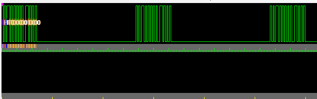
I selected the binmode com port. In AnalysIR, what should I select for “source”?
I tried A.IR Shield ESP8266 Serial, but did not see any signals picked up.
1 Like
Thank you so much for testing. We found the issue though and a fix is incoming. I posted this to the wrong place, sorry about that:
Seems like we found the issue! The format for the A.IR frames is different through the serial port and the AIR import format. Awaiting confirmation of the correct serial format.
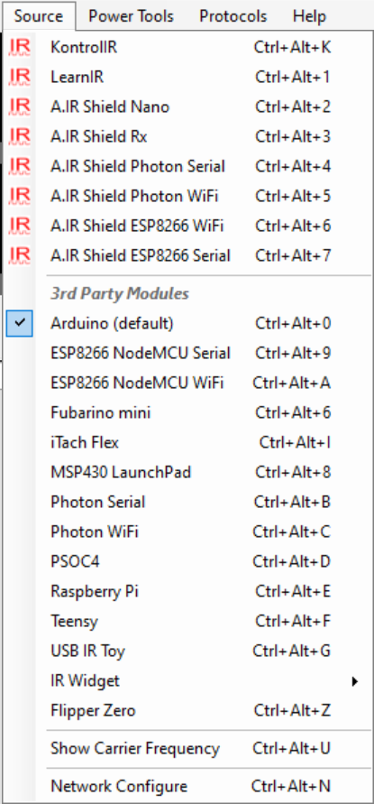
A.IR shield nano will be the best option. Other A.IR using serial ports (some are web) will work to varrying extents.
with reference to sending pulses
assumes buffer with uint16_t entries *you could use uint32_t to simplify things a bit
each entry in the pulse buffer is sent as a set of 5 bytes encodes as below (note quirk below)
1st byte - + for mark & - for space (denoted by least significant bit in buffer
2nd byte 8 bit count of entry from 0._255 overflows to 0 and continues on
3rd byte - high 8 bits of 16 bit pulse length
4th byte - low 8 bits of 16 bit pulse length
4th byte - lowest bit = 1 for mark; =0 for space (losing 1 bit resolution is incidental)
3rd & 4th bytes - see quirk below
5th byte - is always \n (LF)
void reportPulses() {
yield(); //avoid watchdog issues
for (uint16_t i = 0; i < countD; i++) {
//the following logic takes care of the inverted signal in the IR receiver
if (pulseIR[i] & 0x01) txBuffer[0] = ‘+’; //Mark is sent as +…LSB bit of pulseIR is State(Mark or Space)
else txBuffer[0] = ‘-’; //Space is sent as -
txBuffer[1] = (uint8_t) (i & 0xFF); //count
txBuffer[3] = pulseIR[i] >> 8; //byte 1
txBuffer[2] = pulseIR[i] & 0xFE; //LSB 0 …remove lat bit as it was State
Serial.write(txBuffer, 5); //([4] is preset to \n)
yield(); //avoid watchdog issues
}
}
with reference to sending carrier (if available)
this set of 5 bytes is sent after all the marks /spaces are sent above
1st byte id M to signify modulation
2nd byte - is the number of samples used in measuring hte carrier
3rd byte - the high byte of all the sum of all the periods measured in uSecs
4th byte - the low byte of all the sum of all the periods measured in uSecs
In your case depending on how you measure the carrier you can use a count of 1 with the period in uSecs in the next 2 bytes
Note the debug msg sent at the end if no carrier available Serial.println(“! Signal End !\r\n”);
void reportPeriod() { //report period of modulation frequency in nano seconds for more accuracy
#if IRLEARNER //if carrier available
yield(); //avoid watchdog issues
uint8_t sigLen = 0; //used when calculating the modulation period. Only a byte is required.
uint8_t countM2 = 0; //used as a counter, for the number of modulation samples used in calculating the period.
uint8_t j;
sum = 0; //reset before using
for (j = 1; j < (modPULSES - 1); j++) { //i is byte
sigLen = (modIR[j] - modIR[j - 1]); //siglen is byte
if (sigLen > 50 || sigLen < 10) continue; //this is the period range length exclude extraneous ones
sum += sigLen; // sum is UL
countM2++; //countM2 is byte
modIR[j - 1] = 0; //finished with it so clear for next time
}
modIR[j - 1] = 0; //now clear last one, which was missed in loop
if (countM2 == 0) return; //avoid div by zero = nothing to report
sum = sum * 1000 / countM2; //get it in nano secs
// now send over serial using buffer
txBuffer[0] = ‘M’; //Modulation report is sent as ‘M’
txBuffer[1] = countM2; //number of samples used
txBuffer[3] = sum >> 8 & 0xFF; //byte Period MSB
txBuffer[2] = sum & 0xFF; //byte Period LSB
Serial.write(txBuffer, 5);
#else //IR Learner not connected…just send end signal
Serial.println(“! Signal End !\r\n”);
#endif
yield(); //avoid watchdog issues
}
QUIRK
if a mark or space is longer than 0xFFFF we send multiple marks (or spaces) in succession up to the actual length of the pulse
In our case we just send 2 in a row as I have never seen a signal longer than 0x1FFFF.
To send a mark length 0x10010 send 2 5 byte packets 0xFFFF followed by 0x0010
To send a space length 0x10011 send 2 5 byte packets 0xFFFF followed by 0x0011
you should do a bit of boundary testing on this implementation.
Let’s put some structure(+) to this! (+) Pun intended.
pulse sending
typedef struct _IR_PULSE {
    uint8_t identifier_mark_or_space;
    uint8_t entry_count;
    uint8_t pulse_length_msb;
    uint8_t pulse_length_lsb; // lsb bit 0 also stores mark(1)/space(0)
    uint8_t always_LF; // always '\n'
} IR_PULSE;

static uint8_t _IR_PULSE_COUNT = 0;

static void fill_ir_pulse_buffer(IR_PULSE* pulse_buffer, bool is_mark, uint16_t pulse_length) {
    // ...
    if (is_mark) {
        pulse_buffer->identifier_mark_or_space= '+';
        pulse_length |= 0x1u; // always set low bit in pulse count for mark
    } else {
        pulse_buffer->identifier_mark_or_space= '-';
        pulse_length &= 0xFFFE; // always clear low bit in pulse count for space
    }
    pulse_buffer->entry_count = _IR_PULSE_COUNT++;
    pulse_buffer->pulse_length_msb = ((uint8_t)(pulse_length >> 8);
    pulse_buffer->pulse_length_lsb = ((uint8_t)pulse_length);
    pulse_buffer->always_LF = '\n';
}
static void send_ir_pulse(bool is_mark, uint32_t pulse_length) {
    // ... handle sending repeats if pulse_length > UINT16_MAX
    IR_PULSE pulse; // or some global circular / fifo array of buffers?
    while (pulse_length != 0) {
        uint16_t this_pulse = pulse_length > UINT16_MAX ? UINT16_MAX : (uint16_t)pulse_length;
        pulse_length -= this_pulse;
        fill_ir_pulse_buffer(&pulse, is_mark, this_pulse);
        // actually output the data ....
    }
}
carrier sending
typedef struct _IR_MODULATION {
    uint8_t identifier_modulation; // always 'M'
    uint8_t measured_sample_count;
    uint8_t period_sum_useconds_msb;
    uint8_t period_sum_useconds_lsb;
    uint8_t always_LF; // always '\n'
} IR_MODULATION;

static void fill_ir_modulation_buffer(IR_MODULATION * buffer, uint16_t period_in_usec) {
    buffer->identifier_modulation = 'M';
    buffer->period_sum_useconds_msb = ((uint8_t)(period_in_usec >> 8));
    buffer->period_sum_useconds_lsb = ((uint8_t)period_in_usec );
    buffer->always_LF = '\n';
}
Better … allows the code to become more readable.
Note: If this is timing sensitive, and only called in one spot, can use pragmas to force these functions to be inline’d. optimizer should do a good job with it.
1 Like
Nice! That is readable. The space mark seems redundant with the end bit, wasting a byte and or a us of resolution that our monster PIO can do with extreme precision ![]()
I’ve written so many awful protocols that persist to this day so I totally understand.
1 Like
modulation.measured_sample_count = 5;
We measure frequency at 0.2us resolution, and then divide by 5. I think it will probably be more accurate if we pretend we have 5 samples and let the application do the floating point math to find the number of us.
    if (pulseIR[i] & 0x01) txBuffer[0] = '+'; //Mark is sent as +...LSB bit of pulseIR is State(Mark or Space)
    else txBuffer[0] = '-';           //Space is sent as -
    txBuffer[1] = (byte) (i & 0xFF); //count
    txBuffer[3] = pulseIR[i] >> 8; //byte 1
    txBuffer[2] = pulseIR[i] & 0xFE; //LSB 0 ..remove lat bit as it was State
    Serial.write(txBuffer, 5);
Was getting odd measurements, looks like the pulse duration bytes are switched. Also, this example from the AnalysIR download (as opposed to above) only uses the last bit internally and then clears it.
sum = sum * 1000 / countM2; //get it in nano secs
...
  txBuffer[3] = sum >> 8 & 0xFF; //byte Period MSB
  txBuffer[2] = sum & 0xFF; //byte Period LSB
Same with freq, which also seems to be nano seconds and divided by the number of samples?
A.IR format strings may not include the final space, but if they aren’t sent with this protocol the decoding is incorrect.
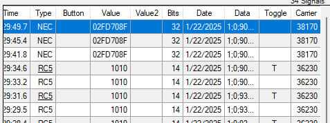
It looks good ![]() Frequency and decoded values seem right.
Frequency and decoded values seem right.
1 Like
For the docs, while it’s fresh:
A.IR Protocol for AnalysIR
Device type
\n!BP Vxxxx!\n
Announce the hardware type so software can self-configure. Only the characters between the first ! and space are used. Anything after the space (‘Vxxxx’) is ignored.
Receive IR
PULSE
The IR signal timing is sent in multiple PULSE packets representing the duration of MARK (IR present) or SPACE (no IR) times in microseconds.
| Field Name | Type | Description |
|---|---|---|
identifier_mark_or_space |
uint8_t |
Identifier for mark or space ('+' for mark, '-' for space) |
entry_count |
uint8_t |
A sequence number for each burst of pulses, starting at 0 and rolling over at 255. |
pulse_length_lsb |
uint8_t |
Least significant byte of the pulse length in microseconds* |
pulse_length_msb |
uint8_t |
Most significant byte of the pulse length in microseconds |
always_LF |
uint8_t |
Always set to newline character ('\n') |
- In some implementations bit 0 of
pulse_length_lsbindicates MARK (1) or SPACE (0). However, this only seems to be used internally in firmware implementations. It appears to be ignored in the latest AnalysIR versions.
Description
- identifier_mark_or_space: This field identifies whether the pulse is a mark or a space. It uses
'+'for a mark and'-'for a space. - entry_count: This field keeps track of the number of entries in the current pulse train. Should reset at the beginning of each pulse train.
- pulse_length_lsb: This is the least significant byte of the pulse length in microseconds. In some implementations the least significant bit (bit 0) also indicates whether the pulse is a mark (1) or a space (0), we did not implement this.
- pulse_length_msb: This is the most significant byte of the pulse length in microseconds.
- always_LF: This field is always set to the newline character (
'\n').
Warning: do not omit the final SPACE. If the final space is omitted, AnalysIR will not decode correctly when multiple signals are captured close together (such as a repeating button), even if entry_count is reset to 0 due to a timeout.
Modulation
A single modulation packet is sent at the end
| Field Name | Type | Description |
|---|---|---|
identifier_modulation |
uint8_t |
Identifier for modulation (always 'M') |
measured_sample_count |
uint8_t |
Number of period measurements |
period_sum_nseconds_lsb |
uint8_t |
Least significant byte of the sum of all period measurements in nanoseconds |
period_sum_nseconds_msb |
uint8_t |
Most significant byte of the sum of all period measurements in nanoseconds |
always_LF |
uint8_t |
Always set to newline character ('\n') |
Description
- identifier_modulation: This field is always set to
'M'to identify the modulation. - measured_sample_count: This field contains of the number of modulation period samples represented by period_sum_nseconds. We use a single sample, others may take multiple samples.
- period_sum_nseconds_lsb: This is the least significant byte of the sum of all period measurements in nanoseconds.
- period_sum_nseconds_msb: This is the most significant byte of the sum of all period measurements in nanoseconds.
- always_LF: This field is always set to the newline character (
'\n').
Note: in practice it seems the measured_sample_count does nothing. If you take multiple samples, then you should average them before sending.
Transmit IR
I believe this is what is properly called the A.IR format. It can be imported into AnalysIR and viewed. It is also the format used to tell a device to transmit an IR signal. It is not used to send IR data back to AnalysIR, instead use the Receive IR format above.
A.IR packet format is used to represent infrared signals captured by a device. The format includes the carrier frequency and the lengths of pulses (MARK) and spaces (SPACE) in microseconds.
Packet Structure
$36:420,280,168,280,420,;
Components
- Start Character:
$- Indicates the beginning of the packet.
- Carrier Frequency in kHz:
36- Represents the carrier frequency divided by 1000. In this example, the carrier frequency is
36 kHz.
- Pulse and Space Lengths:
420,280,168,280,420,- A comma-separated list of ASCII decimal values representing the lengths of pulses (MARK) and spaces (SPACE) in microseconds. It should begin with a MARK, and the final SPACE (timeout) can be omitted. Note the final ‘,’
- End Character:
;- Indicates the end of the packet.
Example Breakdown
$36:420,280,168,280,420,;
- Start Character:
$ - Carrier Frequency:
36(36 kHz) - Pulse and Space Lengths:
420µs (pulse)280µs (space)168µs (pulse)280µs (space)420µs (pulse) Note the final ‘,’
- End Character:
;
1 Like
Am seeing an error from AnalysIR “error reading from device. Arithmetic operation resulted in an oveflow”. Seems like a problem for them perhaps?
This is from the A/C remote I’m trying to capture.
Am using BP bb71e6d which is only a few days old and 1.16.100.8303 of AnalysIR.
Hi Tom,
Thank you so much for checking out the IR plank and the bug report.
AC remotes are notoriously weird. If we can get an idea of the timing I can see what I need to tweak in the firmware.
In AnalysIR - if you go to Power Tools->enable logging, is there any timing info in the log panel?

In infrared mode (raw) could you capture a IR frame from the remote with the irrx command? That also gives us an idea of that is received.
A third option is to use the SUMP binmode with pulseview. Enter IR mode and apply power. Next set pulseview to trigger on one o f the sensor pins (IO1 or IO4 might be a good choice) then arm the pulseview logic analyzer and fire the remote at the sensor. This will give us detailed info about the modulation of the signal and the timing of the frame.
2 Likes
Hey Ian, Thanks. I don’t need special treatment. If I can help build the product, all good but I don’t need a one off fix.
However, after the laptop powered down overnight this has fixed itself. Super annoying but am getting ELECTROLUX112AC decodes now so that looks like something I can work with. Will come back to your request if the problem re-appears.
Thanks for making BPv5 so awesome. Cheers.
1 Like
Hey Tom, this is brand new code for a protocol I had to kind of reverse engineer. There are bound to be issues, and anyone reporting them will get the same treatment ![]()
I’m glad it’s fixed now, but if you can reproduce it in the future please let me know. I am aware of a couple differences in how I implemented the AnalysIR protocol and how it was done in the past (my timeout is shorter, and we don’t send repeated packets if the signal is stuck low). I’m waiting for those to come bite me, which is why I wasn’t surprised to see an issue with an AC remote.
Noticed today that there is a new/updated dev version of AnalysIR available. It might be worth upgrading.
Thanks. The string of codes it sends for a single button press is large. This is the power button, it’s probably sending down the entire config. Re-uploaded, didn’t catch that the log doesn’t clear.
1 Like
Thank you. That looks pretty clean. Just to be clear, this is working now?
Yes all, good thanks!
1 Like