The spi module has a slave mode, and we can also write one for the PIO. The hardware infrastructure is there.
At the most basic level we could just spit out precanned data for a given byte command. Maybe load them from a config file.
sPI device interfaces aren’t that consistent though. Maybe it’s a command followed by 3 address bytes (spi flash), maybe it’s a write and read back operation (spi SRAM, psram). Sometimes it’s a configuration register being set that should have some effect later (ADC?).
It feels like the options are something really basic (a text file with commands to match and the response to give), or a full fledged script system as mentioned by dreg.
Is there an existing scripting framework to integrate? Micropython exists. I wouldn’t want to roll my own as it would never be as nice as something properly maintained. We’d need basic logic (if then else), some way to store data?, A timer for your use case, etc, etc.
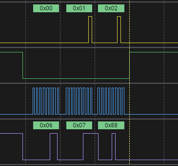
I can make something very basic to test. I’m not sure how useful it would be, but we can see how it works:
| Address |
Bytes RX |
Bytes TX |
Data TX |
| 3 |
3 |
? |
0 1 2 3 4 5 6 7 8 9 10 |
For example an SPI flash read command is 0x03, followed by 3 address bytes (depending on density), the we return some bytes.
Immediately we run into a problem. 0x03 sets up a read, which can then read out the entire chip (say 64Mbits). If we reach the end of the Data TX and the read is still happening, what is the best behavior? I guess looping back to the beginning of the dummy data.
If a single or a very small number of slave commands would be useful, we could add a slave command that loads a single command and response into RAM.
slave -a 0x03 -r 0x03 -t 0 1 2 3 4 5 6 7 8 9 10
Something similar to above but listening for a single command at a time.
The other aspect is speed. I believe you mentioned 65.2mhz, and that’s going to be an issue for several reasons.
At 62.5MHz we only have two clock ticks to respond to the command. It will take the RP2040 way longer than that to decide how to respond to the command and load the data to output. Second, the buffers and protection resistors usually top out at 14-20MHz, depending on how everything is connected.
It might be realistic to aim for a 10MHz slave if we’re only watching for a single command, or use a lookup table (how to load this?).
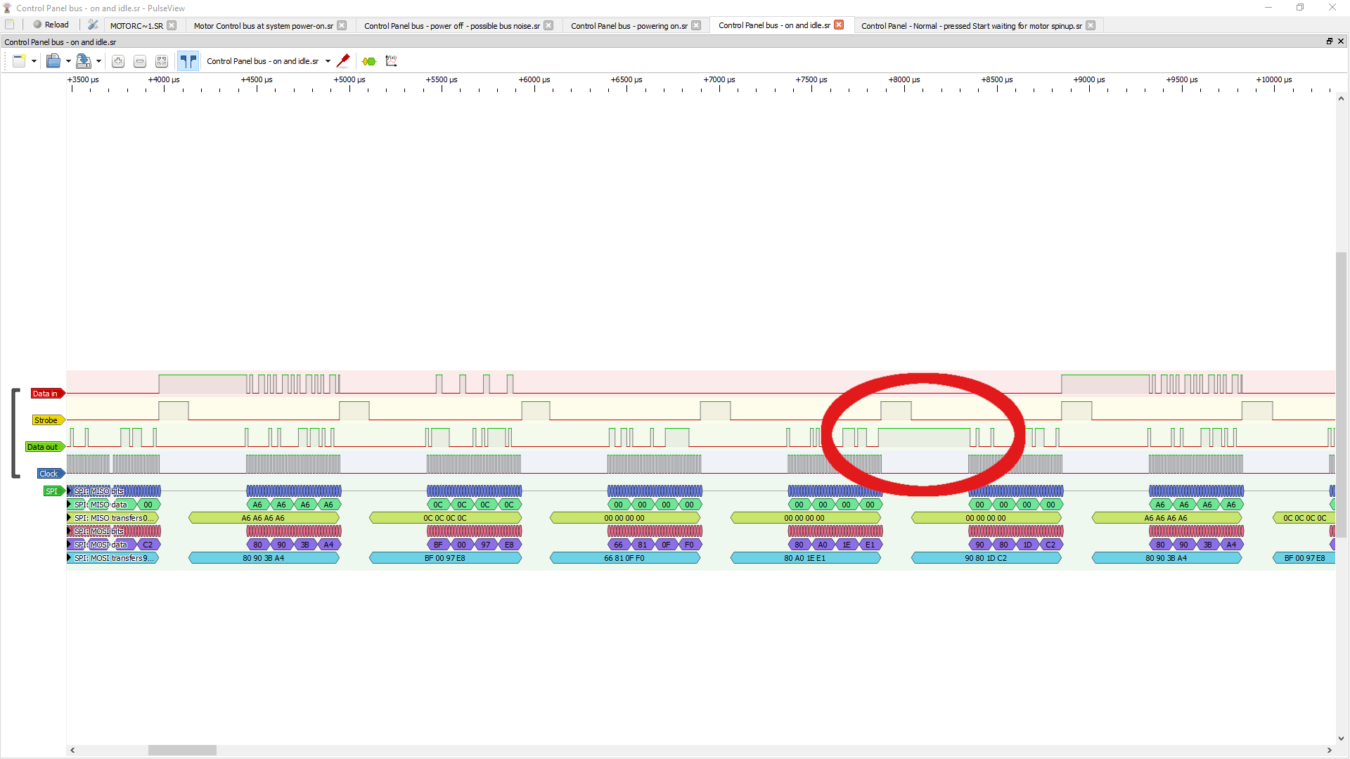
I will test the SPI peripheral in slave mode so I understand how it works, but this will only echo the master data into the Bus Pirate terminal. The real grind is designing an interface that is generally useful beyond one specific project.