Mine arrived yesterday. I’ve been looking to check it out, but … real life events have made life really busy right now.
I’m expecting I’ll be able to smoothly follow my prior write-up at I2C SeeSaw details.
Maybe this weekend.
Mine arrived yesterday. I’ve been looking to check it out, but … real life events have made life really busy right now.
I’m expecting I’ll be able to smoothly follow my prior write-up at I2C SeeSaw details.
Maybe this weekend.
Thanks everyone! No rush, I just wanted to make sure we didn’t forget to send them all out ![]() glad they arrived.
glad they arrived.
I have not tested (and will not be testing) the grove, gravity, or card-edge slots. I might be able to test the full-size Stemma later, or maybe someone else will verify on a different device.
As to Qwiic / Stemma QT … works great using one (and two) I2C SeeSaw devices connected via a Qwiic / Stemma QT port, using 5V / 100mA (5V / 200mA), following the I2C SeeSaw details post noted earlier.
I’d call this a success for Qwiic / Stemma QT.
Excellent! Thank you for testing.
I’ve tested the Grove, Gravity, Breakout Garden, and Qwiic, and everything has worked fine. The Breakout Garden helped me to verify that one of my Breakout Garden bases was bad by proving that the BME688 board itself was working perfectly.
Thank you also, that is excellent! Glad the breakout garden is working.
I’m having trouble finding the old stemma stuff. I’m going to write adafruit and engage them on that part. Maybe they’ll want to carry this plank as we.
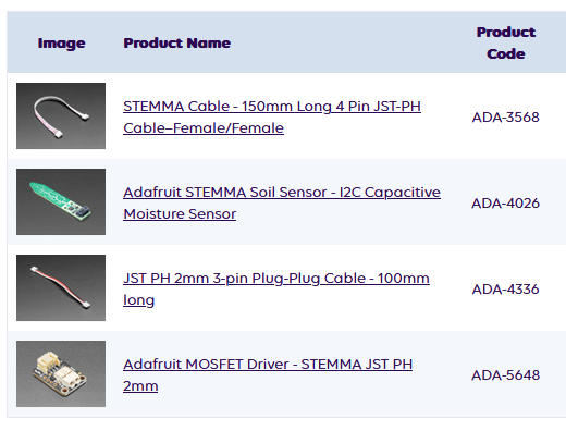
This is what I can find to test the remaining two connectors. They can’t ship before next week, so I will look a bit further. This is a bit expensive and not the ideal test for the 3P STEMMA.
4-pin 2mm STEMMA connector can be tested by using a STEMMA-to-STEMMA QT cable. I have some of those … I can verify basic functionality in a couple days.
The 3-pin STEMMA is just a single GPIO exposed … nothing really to test. Hookup an LED (+resistor)?
It’s possible the larger STEMMA port is wired incorrectly.
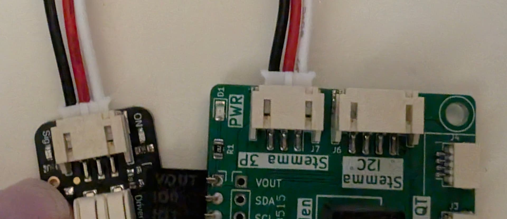
I previously tested the devices using STEMMA QT cables.
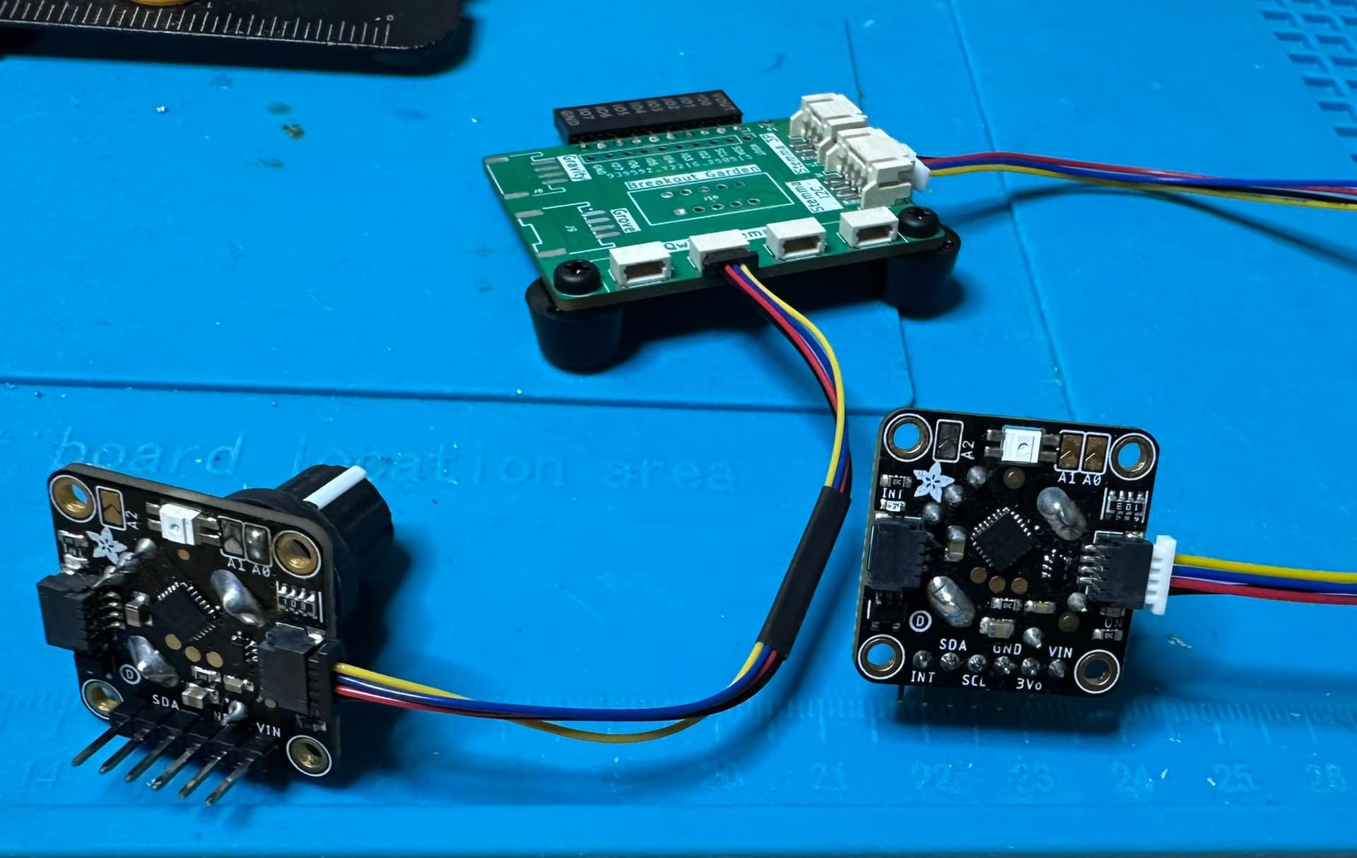
I then connected one using a STEMMA-to-STEMMA QT cable, but nothing was working.
So, I removed the plank, and connected both devices using the two different cables:
This made it easy to test continuity.
The results:
| Stemma QT | Stemma |
|---|---|
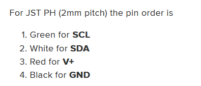
SDA |
Vin |
SCL |
GND |
GND |
SCL |
Vin |
SDA |
So, it looks like the pin order is reversed on the full-sized STEMMA port?
The qwiic cable seems to be a 1:1, while the big stemma is a cross over. I don’t have the schematic or anything handy, but I’ll confirm later. Lots of mentions of wrong cables on the hack a day post about the various standards. This seems to be similarly reversed, but this is just a hunch.
If this ends up needing a board revision, I also note that the installed feet do not “fit” within the board outline. As a minor preference, I’d prefer the feet to be withing the board’s outline… just looks nicer.
We are going on a mission for better feet. I want to see an actual manufacturers catalog instead of relying on the bog standard stuff. It’s something I’m quite unhappy about ![]()
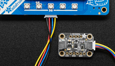
Here’s a Grove-to-Stemma cable
I’m pretty sure the plank is wrong! Thanks for testing!
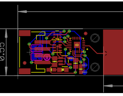
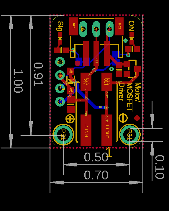
The PCB of the plant water sensor board. If this is correct, the plank is wrong.
This example of the adapter cable, if rotated, I think also suggests the plank is wrong.
Wow, don’t know how I missed that, it is obviously wrong. It is in fact a swapped pin order. Thank you both so much!
Updating schematic.
The one connector I did not test. I’m glad this was caught.
Stemma 4 is indeed backwards. It is already fixed in the latest revision.
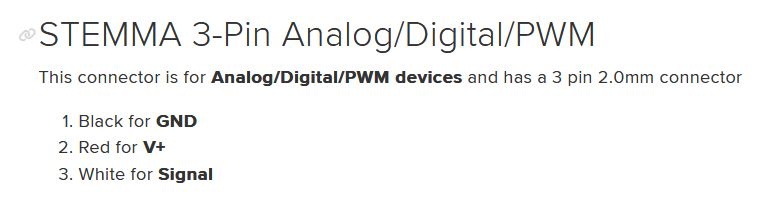
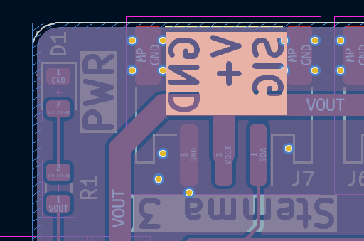
Here’s one I didn’t expect: Stemma 3P is also backwards. This time it actually seems to be wrong in the adafruit docs.
| Pin | Description |
|---|---|
| 1 | GND |
| 2 | V+ |
| 3 | Signal |
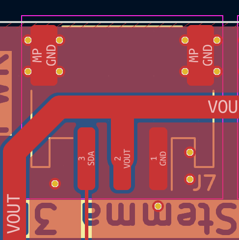
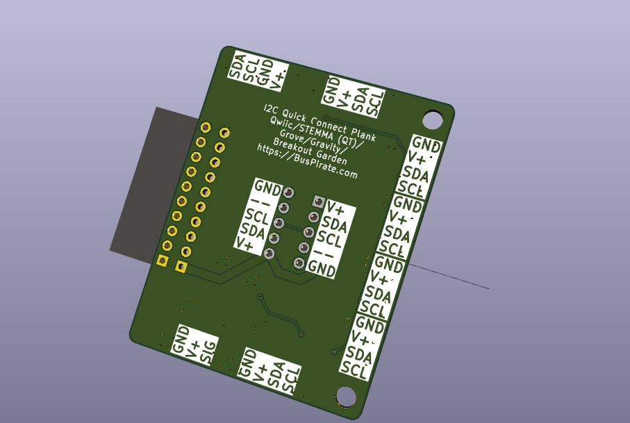
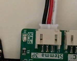
Here’s our board that matches.
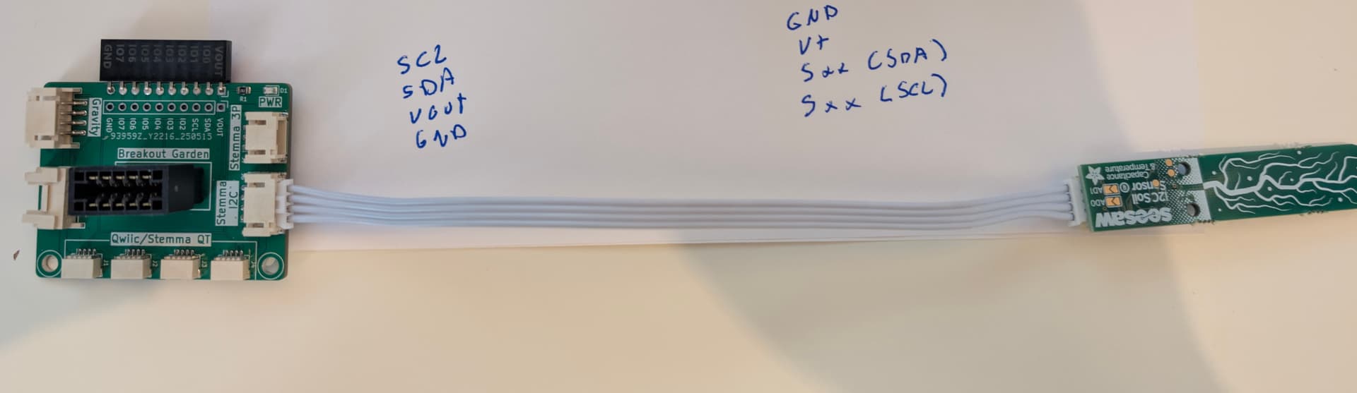
Here is the PCB for the FET board I bought. Hard to see but GND on left and SIGNAL on right.
Just going by the colors: black is ground, red is V+ and white is signal. It’s the same pinout on the silkscreen on the bottom.
When I plug it in, it certainly behaves like the ground is connected to the pin. When the pin is low the power LED is strong, when pin is high the LED goes off. It should be the signal LED going on and off. Going to assume this needs to change.
In light of this confusion, I added clear labels to the bottom of the board.
Added a table of pinouts and connector part numbers to the docs.
PCB is updated, but I think I want to sit on it for a day or two. Make sure I haven’t missed anything.
I’ll happily pay for the updated version.
No worries, we will make 5 and send out to the same testers. No guarantee to be bug free ![]()
Is the 3p label still backwards? If we’re looking bottom-up in the image, it puts the ground on the right (when in its normal orientation).