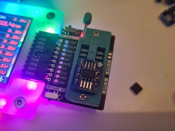
Yesterday I added a macro to read SPI flash parameter tables. This week I’ll add a universal rom flash command. I put some chips on breakouts, but I wanted something reusable.
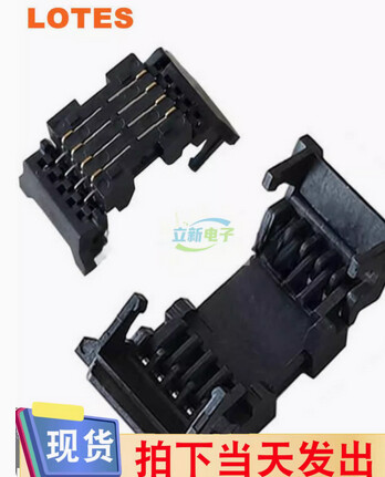
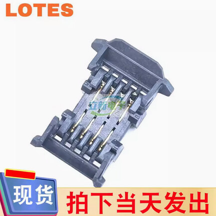
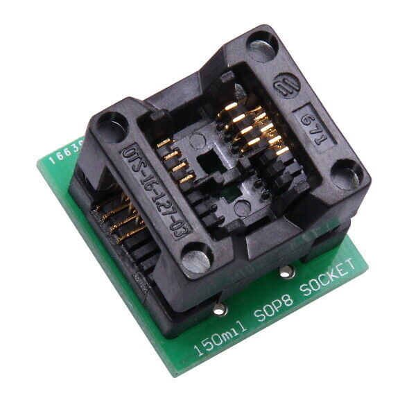
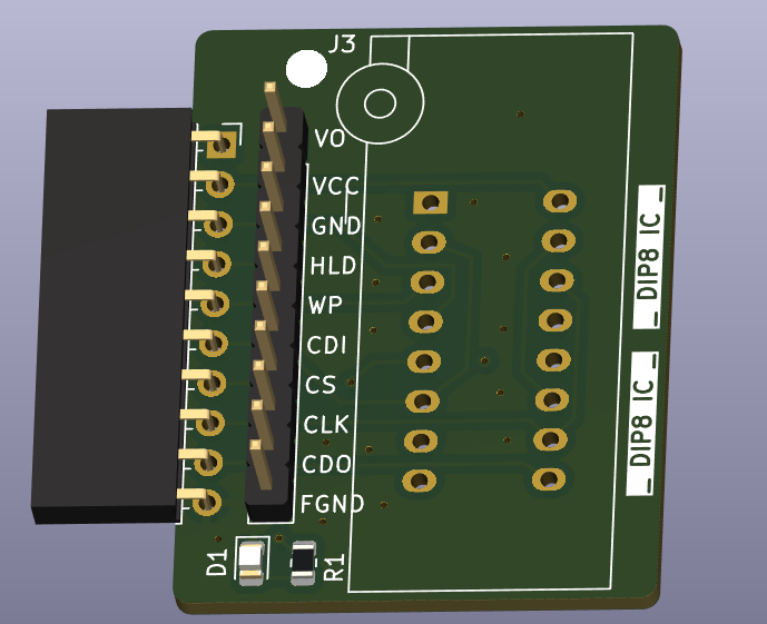
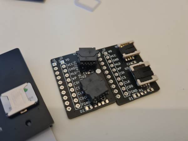
This is an adapter with two ZIF sockets that hangs off the Bus Pirate connector. I made a version with SOP8 150/208mil, and one with DFN/WSON 6*8/5x6.
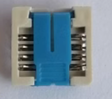
The SOP sockets I like the best are Lotes AP-ACA-SPI-004-K (208 mil) and AP-ASPI0001-P (150 mil). The 208 is cheap, but the 150 is four times the 208 price for some reason.
All the DFN/WSON sockets are expensive. There is a pair from a Chinese manufacturer that aren’t horribly expensive (~$2.50) and advertise being rough and tumble (they bend it repeatedly in the video).
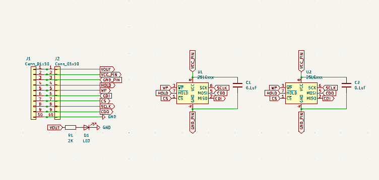
There are two sockets, but only one chip can be used at a time with this configuration. That’s because the power and ground flash pins are connected to IO pins. Any 8 pin chip that will run on <25mA (from the IO pins) can be probed in the socket, and flash chips can be programmed in quad mode for faster writes.
I already sent the SOP size board out, but I need the datasheet for the DFN 6*8 to confirm spacing.
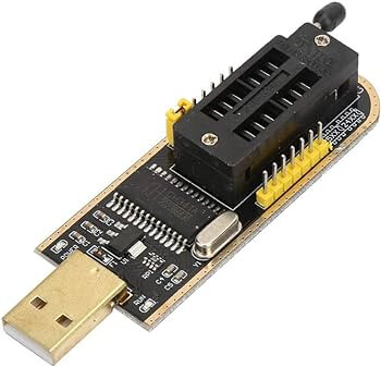
Nice! I also ordered a full set of those spring contact things to check out. I also came across that CH341 and various software when I was looking for the cheap common sockets.
Hmm, it looks to me like the flash ic is powered from a regular io pin (VCC_PIN) and not the voltage regulator output of the bus pirate (VOUT). What is the reason for this?
I fear that the 330 ohms series resistor on the io pin could lead to a brownout on the flash chip when it is reading or writing. they tend to have current spikes when you issue some block transactions or similar. this would be similar to when you try a voltage glitching attack on some protected ic: some bits can change their value. this is something you really do not want when reading or writing flash memory. when writing or erasing it could also happen that the write/erase looks good on first verify, but is not properly done and doesn’t persist, so the bits could change their value a few minutes to hours later.
all 8 pin spi flash ics i’ve seen so far use the same pinout. so you wouldn’t need to use a io pin to be able to account for different pinouts.
That’s a good point and I will need to do some testing. With the series protection resistor the buffer can deliver >15ma @ 5v, and most flash chips I’ve seen use 3-12ma during writes.
My hope is that by having all 8 pins be IOs, I can work with chips other than flash chips. Also, for the smart IC card version, I’d like to try glitch hacking. Not sure it will work, but fun to have a look.
Edit: I am looking it over a bit, and I was probably too careful with the series resistors. The Bus Pirate is necessarily in situations where pins can be in contention, and I really don’t want to blow out the Bus Pirate buffers or a device under test.
Thank you again for your feedback. You inspired me to revisit my notes on the series resistor
In terms of the 74lvc1t45, it can sink and source a ton of current at the high end of the voltage range. Easily enough to blow out a pin on a connected device. 330 keeps it to 15mA, which is still probably enough to do some damage to a DUT pin if left in contention for a while.
At the lower end we just meet or exceed the limits slightly. ~8ma @ 2.7v, 5.9ma @ 1.95v. 3.6ma@1.2v.
My gut said 220ohm, and I used that in the first few revisions, but I did actually have some pin blow outs. Whether that was due to the current or bad reflow I don’t know. I upped it after having a look at the datasheet and modeling the effect on the pull-up resistor open drain voltage levels.
I’ll do some extensive testing while I build out the flash programming tools and see if the pin is a reliable power supply.
But do you have any concrete examples for an 8-pin ic in mind that doesn’t have vcc and gnd on 8 and 4? even the Attiny85 I just looked up has it this way.
Maybe add two jumpers or dip switches to vcc/gnd that are set by default and that could be removed when dealing with uncommon pinouts. that way the most common setup is safe regarding brownouts.
regarding power draw: please don’t just think about current chips. i think it is a common application to use the bus pirate to work on devices that are like 15 or 20 years old and thus using older chips that might have a quite different voltage/current requirements than modern ics.
Were you really able to blow a pin on a 74lvc1t45 with 220 ohms? marcan and i did some testing for glasgow with them and 33 ohms in series. we ran them into a short circuit at 5v for 12 hours straight or so. they got warm but that’s it, fully functional afterwards.
Maybe add two jumpers or dip switches to vcc/gnd that are set by default and that could be removed when dealing with uncommon pinouts. that way the most common setup is safe regarding brownouts.
This was my thought as well. Because I also want to include a cap, and that isn’t friendly if that pin is used as GPIO.
I was unaware the power and ground pin on 8 pin chips was that universal.
I had several blow outs caused by the 74lvc1t45 in other chips on the board, and twice had to replace 74lvc1t45s. These were all the first few revisions when I was trying to assemble them with the Neoden. After I started having the boards assembled professionally it didn’t happen again, but that was also after 5 or so revisions and bug fixes.
Interesting mention of Glasgow. Many years ago I read through a development discussion about the 74LVC1T45s and current limiting resistors. I believe it was between the FPGA and the 1T45s. Someone had suggested series protection resistors and they added 270ohm (?) resistors. It is where I first read that a 1T45 will easily sink/source a lot of current and burn out connected pins. Maybe you were part of that thread?
I’d like to hear more about your testing. It would be great to lower the series resistors value if it is not likely to damages peoples DUTs.
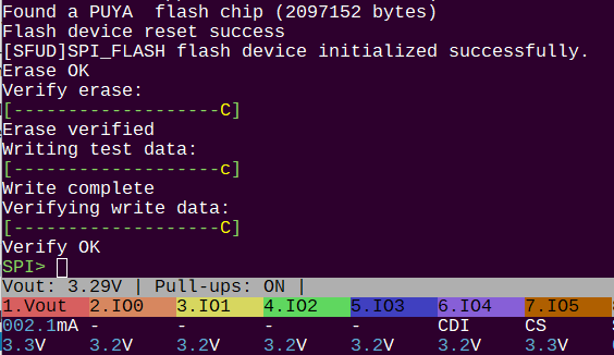
Programming at 12.5MHz works consistently. Above that, the chip isn’t found. I’m happy with that speed for this arrangement, even surprised it works > 4MHz. Chip on a breakout board connected to the heavy probe cable, no decoupling cap. It will be interesting to see if the adapter boards can do better.
I’ve also ordered some lower value resistor arrays to check the effect on speed.
I have not implemented QPI mode, but that would give a significant speed increase and most newer flash chips support it. QPI is already supported in the library I used, there is a QPI PIO example too (not that it would be hard to write).
Regarding the 1T45s blowing out other chips: you mention that this happened with dody placement/soldering. This could very well be caused by shorts. Consider for example a short between pin 5 (DIR) and pin 6 (VCCB/VREF_OUT) of the 1T45. There is no resistor on the DIR line to the RP2040, so if you set VREF_OUT to 5V in that case it will blow the RP2040 for sure. The resistor between the 1T45 and the outer IO connector of the Bus Pirate doesn’t matter at all in this case. Other variations of shorts with similar consequences are possible too. I think in most cases of the 1T45 killing other chips on the Bus Pirate itself, the resistor to the outer connector isn’t involved.
In my line of thinking the job of these resistors is to mostly protect the 1T45 from outer influences, things like ESD, shorting an output or the user accidently injecting a higher voltage. Another job of them is to dampen reflections and act as series termination.
The job of protecting the 1T45s could be greatly improved by adding TVS diodes.
Regarding protecting the DUT: I think this is best left to the overcurrent protection of the power supply as this is much more flexible and also includes protection for the voltage output.
I vaguely remember discussing the IO design of the Glasgow with you some time ago somewhere. But I don’t have a link to the discussion at hand.
We tested the IOs of the Glasgow with shorting them for many hours at 5V. also overvoltage from outside, but I don’t remember how hight we could go until the 1T45 blew. Another test was using the spark from a gas lighter as a crude replacement for ESD.
Absolutely, it was crazy frustrating with the boards I made. I went to a friend’s office to use a stereo microscope and it just didn’t really illuminate the situation at all. @Jin convinced me to use a protofab and we never looked back. My pride is slightly injured though, I think assembling my own prototypes is part of planning for manufacture.
I’m glad to hear you don’t think the 1T45 wont kill DUTs, and that the over current is sufficient. I should receive these boards this week (one package comes tomorrow), and I’m excited to stress test stuff.
These turned out to be a bit tricky to solder. I’m going to look over it a bit this afternoon. A combination of not-great footprint for hand soldering and tiny hidden leads.
I think it’s important to include a chip with each adapter, so it can be useful/educational out of the box. I wanted to use Puya chips because they’re so cheap and the datasheets are really nice, but they only make SOP chips. A parts uncle said I should stick with Winbond because they have good supply in SOP and WSON.
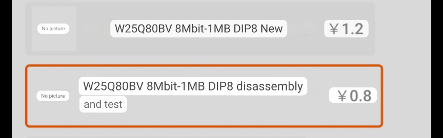
However, he said nobody makes DIP flash chips anymore, and he seems right! What I managed to find are New Old Stock as well as recovered/tested/recycled Winbond W25Q80BV. This chip has a SFPD table, so I think it’s the one.
The SOP chip with be a similar 8mbit cheap-o Winbond flash. For the WSON in 5x6 or 6x8 it’s probably going to be 128mbit because they don’t really make smaller sizes in these packages.
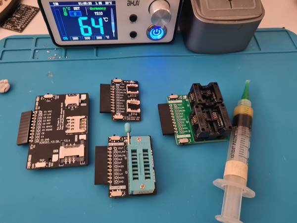
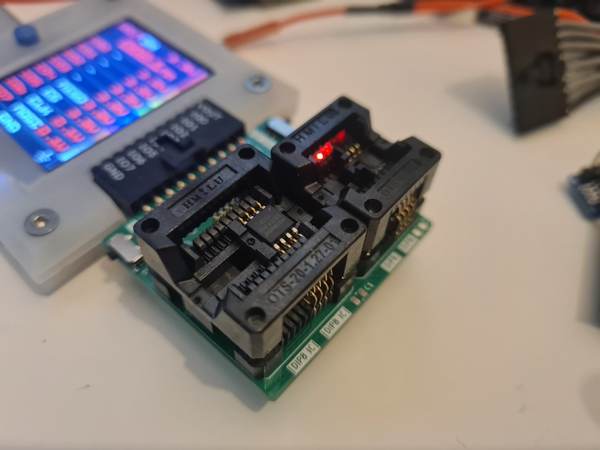
Boards arrived yesterday and I soldered them up. It occurred to me I don’t actually have any WSON or DIP chips to test. I got a WSON chip at RS components and it will arrive tomorrow. For the DIP chip, I’ll just use a little breakout and an SO size chip.
It’s a bit of a hack job - I skipped breakfast and was shaking like a leaf, but I got it done.
DIP board is ok. I don’t have any dip chips, so I used a little Adafruit adapter board.
55 e-waste flash chips are on the way. I imagine it’s going to be like when we bought bags of e-waste phone for the BGA reballing workshops. Some will be pristine and like new, others will look like they were dragged up from the bottom of a lake.
Watch the little switches, they gave me issues on two boards. Curiously enough, the SOP8-150mil worked, but the 208mil didn’t. The power switch pin wasn’t connected. The cheap 150mil Puya flash evidently was able to be reverse powered through the pins, but a 208mil Winbond flash wasn’t.
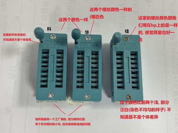
ETA: I wasn’t a huge fan of these sockets. I like the small and cheaper to ship LOTES sockets, but they’re a nightmare to place and the 150mil one is 10x more expensive. I like the WIESON 208mil adapter, but they don’t make a 150mil and it’s 3x more expensive. These through hole things are the cheapest solution, and it’s what they use in the cell phone repair markets. I always try to follow their lead because they are deep into this stuff. After using it for a bit, I’m actually really happy with them. A tweezers are really useful for loading and unloading.
Tomorrow I’ll have WSON chips to test in the final board.