Splash Screen Fail / Suggestion

I had an idea last night to add a splash screen. I accidentally tossed my BP5 and BP6 into my bag, and I still haven’t marked them so I can’t tell at a glance which is which.

I thought, what if I added a splash screen which you could invoke by holding the button while you power up the device? That should be a piece of cake.

But it wants easy as I thought. After a high level scanning of the code, I’m seeing the LCD screen routines are slanted towards the display of pin information (and reasonably so). I found the write text function, but I decided I didn’t understand enough of the system structure to quickly make the change / pull request.

Therefore, I’d like to suggest this feature. Or, if someone could just nudge me in the right direction code-wise, I’m willing to give it a try.

In the meantime, I’ll make my BP5/6 have different button colors today.

2 Likes

I went with different button colors - which makes the difference immediately obvious.

1 Like

1ea Sharpie…. :wink: [I will somehow make sure to hit the 20 character minimum]

2 Likes

Here’s one way for a subtle distinction:

  1. Take the case apart (watch out for falling buttons)
  2. Remove the PCB
  3. On the INSIDE of the bottom case, use colored sharpie to make large (~1.5" high) text (e.g., “2GB” or “6”) … but MIRROR’d (so it will look correct from outside the case)
  4. For better contrast, now use a black sharpie to fill in a box around that text … Do not overlap the text, but fill in all space in the box that is not colored in.

See picture of the 2GB BP5 done this way (it’s the one on the right):

This type of marking is not really noticable unless you’re looking for it, which I rather like. In combination with using different color buttons, it allows me to forget which color maps to which device, and have a backup method to know which is which.

A quick splash screen that appears on the display would be nice - especially for those with more than one device. Perhaps a configuration option can be used. Obviously if you restart your BP dozens of times a day this would be irritating.

The sharpie on the inside of the case is a good idea though. My freehand drawing is iffy. :slight_smile:

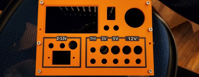
I’m willing to print some backs for the cases that have the version number embossed or similiar. I can do multi color by printimg an inlay and gluing in a high contrast color. See below power supply I’m working on for example.


That is blue Prusament ASA and orange ABS, the white is paint pen on top of the slightly raised characters. I have other colors and material, also.

1 Like

What about something very simple, show the content of a text file from the flash drive when booted. Whether it is your name or bp6.or a reminder that for x enter y,z, last project details.

Good idea. Some quick thoughts:

LCD graphics library

The LCD could really use some love. Paul mentioned that there are some nice libraries out there.

I won’t get to that until after we reach a v1.0, but it is not that far off. 2 -3 months maybe? Depends on getting the docs done more than anything.

System monitor

The LCD routines and system monitor (and VT100 toolbar) are highly optimized to avoid writing any character that hasn’t changed. Optimized, but poorly and hard to follow.

I dread going in there, I understand why it seems incomprehensible.

Splash screen

AjcQ7d82

@jin wants to put the unitsix artwork as a startup splash screen. We could put the version number on there somewhere.

This is a bit easier to tackle than writing text to the display. The background of the pin labels screen is an array of bytes dumped from a bitmap image. Writing a slash screen first, and then writing the label background later is pretty easy.

The issue will be dumping the bytes to an array from the bitmap image. There are some utilities to do that, but I believe I was super genius and arranged the RGB bytes in BRG format and packed everything as 24bit words so common utilities weren’t useful.

There is a terrible qt application in our github repo called “bus terminal” that I used to do this, but I will never touch that thing again. There is defo a better way.

Maybe parsing bitmaps directly so we can load alternate backgrounds and splash screens from the NAND storage?

Display buffer

Is there really not a display buffer in the LCD chipset? Currently screen draws are really slow because we use 24bit color mode. The backlight stays off during startup until the background is drawn because you can see it wipe across the screen.

There must be a way to draw to the frame buffer before updating the screen contents, right? I don’t remember if I didn’t look or I couldn’t find one. Something to look into.

5 Likes

I like the idea of putting the version number on the Bus Pirate screen of unistix artwork as a splash screen. This could also be implemented as the startup screen so that the back light is already on and a button press could take you to the default screen. Just a quick thought.

2 Likes

May I put that image as a splash screen on my MP firmware? I was using the DP logo I like this better (product specific vs brand )

2 Likes

MP? If not a typo, do share what device you’ve created!

(if it’s a typo, and meant to be BP, then nevermind…)

I love the idea of a bootup splash screen, including an indication of the model.

Do you think it makes sense to add datasheets for all components into the buspirate5-hardware repository? If so, I’d love to see the following added:

  • RP2040 and RP2350
  • LCD
  • Pixels (WS281x or SK…)
  • 1gib and 2gib NAND (built-in storage)

Finally, getting back to the core questions:

IIRC, some displays just constantly update from the same RAM as used to write updated screen data. Tearing (or visible partial updates) are just part of the “flavor” for such screens.

Of course, if it’s a higher-end screen, maybe this isn’t the case. Do you happen to have the datasheets? :slight_smile:

Sorry, I meant MicroPython. I’ve been writing up my article on the topic, and I got so tired of typing MicroPython and Bus Pirate all the time, I started using MP and BP. Based on your confusion, I think I’ll do a file-spanning replace of these terms with the full word.

Of course! That would be cool!

ST7789V is the chip in the display.

Page 135 has two tearing effect scenarios.

3 Likes

Wow… that chip has a gazillion configurations available! IIRC, the BP5 uses the 3-line serial interface, 5-6-5 pixel format (based on memory).

If I read it correctly, it seems page 135 is not showing a case where tearing occurs; rather, it’s showing a way to write the data to the display when the data transfer would take >1 frame, but <2 frames, without tearing.


Graphic appears wrong/misleading....

First, this is a neat hack. The text suggests this is used when the MCU update of the RAM will take longer than one frame LCD update, but faster than two frame LCD update time:

  • At time A, writing to LCD from RAM starts (frame #0)
  • At time B, MCU starts writing data for frame #1 to RAM
    • because this is at a rate slower than 1 frame write rate, but faster than time to write 2 frames, the write never “catches up” to where the LCD is being updated from
    • put another way, the MCU is “chasing” the LCD refresh point during this half … so no tearing occurs.
  • At time C, writing to LCD from RAM finishes.
    • between time C and D, MCU is still writing to RAM …
    • generally, the MCU will have written at least half the screen data prior to time D…
  • At time D, writing to LCD from RAM starts
    • This is now starting to write frame #1, which is still being written by the MCU
    • However, the MCU write pointer is over half done.
    • put another way, the LCD refresh is now “chasing” the MCU updates
  • At time E, the MCU finished writing the last of the updated data to the RAM
    • the LCD is still updating from RAM…
  • At time F, the second frame of the LCD refresh is complete, and the display is now showing frame #1

The above process can repeat, allowing MCU to update the LCD every two frames.


However, the above requires sending the updated data based on the TE output signal (i.e., interrupt-based, or using a PIO SM), with a delay from the interrupt before sending using command STE (44h): Set Tear Scanline to add necessary start delay, and ignoring the interrupt when a write is in progress.

Same requirement of using the TE output signal even when the data can be written faster than the LCD refresh occurs… just have to start sending ASAP on interrupt.

Understandable design.

2 Likes

I can confirm it’s RGB 565 format, because that’s what I’m using to send images in MicroPython. I’m about to try an experiment using 4-bit grayscale today. That cuts the size of an image considerable (if it’s monochrome) because two pixels are packed into one byte.

2 Likes

I’m going to add a command to load bitmaps onto the display. To kind of ease my way back into firmware, I’ve been writing Python and Typescript for a few weeks :mask:

Not sure this is the final choice, but I read through this MIT licensed bitmap manipulation code and it should get it started with the basics. I prefer to wrap everything in a nice struct though, let’s boil a bath tub of water and see what Chad comes up with:

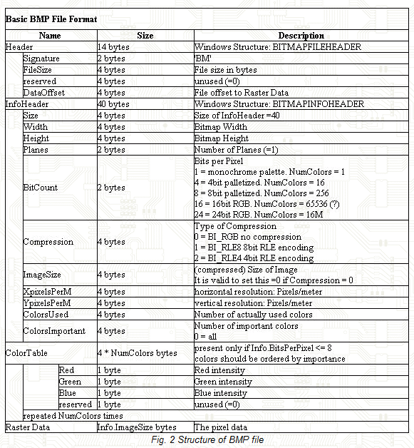
BITMAPFILEHEADER

This header contains general information about the BMP file.

BITMAPINFOHEADER

This header contains detailed information about the image, such as its dimensions and color format.

Here’s how you can define these structs:

#include <stdint.h>

// BITMAPFILEHEADER structure
typedef struct {
    uint16_t bfType;      // Specifies the file type, must be 'BM'
    uint32_t bfSize;      // Specifies the size of the file in bytes
    uint16_t bfReserved1; // Reserved, must be 0
    uint16_t bfReserved2; // Reserved, must be 0
    uint32_t bfOffBits;   // Specifies the offset from the beginning of the file to the bitmap data
} BITMAPFILEHEADER;

// BITMAPINFOHEADER structure
typedef struct {
    uint32_t biSize;          // Specifies the number of bytes required by the structure
    int32_t  biWidth;         // Specifies the width of the image, in pixels
    int32_t  biHeight;        // Specifies the height of the image, in pixels
    uint16_t biPlanes;        // Specifies the number of color planes, must be 1
    uint16_t biBitCount;      // Specifies the number of bits per pixel
    uint32_t biCompression;   // Specifies the type of compression
    uint32_t biSizeImage;     // Specifies the size of the image data, in bytes
    int32_t  biXPelsPerMeter; // Specifies the horizontal resolution, in pixels per meter
    int32_t  biYPelsPerMeter; // Specifies the vertical resolution, in pixels per meter
    uint32_t biClrUsed;       // Specifies the number of colors used in the bitmap
    uint32_t biClrImportant;  // Specifies the number of important colors
} BITMAPINFOHEADER;
  • BITMAPFILEHEADER: This struct represents the file header of a BMP file.
    • bfType: Should be ‘BM’ (0x4D42) for bitmap files.
    • bfSize: Size of the file in bytes.
    • bfReserved1 and bfReserved2: Reserved fields, must be 0.
    • bfOffBits: Offset from the beginning of the file to the bitmap data.
  • BITMAPINFOHEADER: This struct represents the information header of a BMP file.
    • biSize: Size of this header (40 bytes for BITMAPINFOHEADER).
    • biWidth and biHeight: Width and height of the image in pixels.
    • biPlanes: Number of color planes, must be 1.
    • biBitCount: Number of bits per pixel (e.g., 24 for 24-bit RGB).
    • biCompression: Type of compression (0 for no compression).
    • biSizeImage: Size of the image data in bytes.
    • biXPelsPerMeter and biYPelsPerMeter: Horizontal and vertical resolution in pixels per meter.
    • biClrUsed: Number of colors used in the bitmap.
    • biClrImportant: Number of important colors.

Example:

    BITMAPFILEHEADER fileHeader;
    BITMAPINFOHEADER infoHeader;

    fread(&fileHeader, sizeof(BITMAPFILEHEADER), 1, file);
    fread(&infoHeader, sizeof(BITMAPINFOHEADER), 1, file);

    printf("File size: %u bytes\n", fileHeader.bfSize);
    printf("Image width: %d pixels\n", infoHeader.biWidth);
    printf("Image height: %d pixels\n", infoHeader.biHeight);

That’s how I like to do it.
2 Likes

Bitmap structure.

There is a new branch called bitmap_stuff with a new command image. I’m using Chad’s structs, which seem about right.

The image size 0 is correct if compression =0, but we get 3, so I need to look into that.

This is the bitmap used as the background on the display currently. I’m guessing 16 bits per pixel is correct - I probably preprocessed it to the final format in Photoshop to get the nicest effect.

Tomorrow I’ll get it to load data on the display, hopefully for 16 and 24 bit .bmp files. Then I’ll look at loading custom splash screens and backgrounds from NAND.

2 Likes