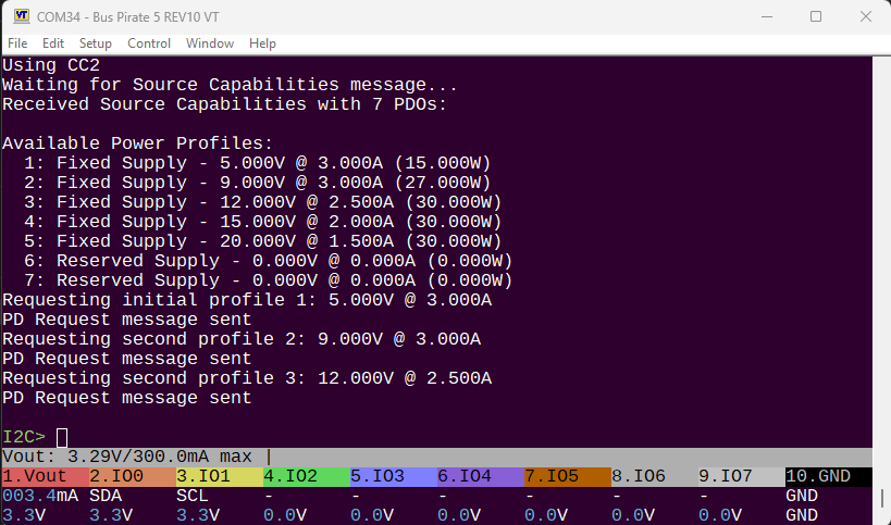
The source expects a response right away, so there is no time to let the user choose at a menu or whatever.
So we send the first profile for 5volts right away.
That buys us time to change to the desired profile
Requests are rejected if the message_id field doesn’t increment, so we’re tracking that
Next I’m going to try to re-query the list of PDO profiles without resetting the device. Code is still an awful mess.
ETA:
Requesting source capabilities...
Sending Get_Source_Cap message...
Waiting for Source Capabilities message...
Received message type: 1, data objects: 0
Received Source Capabilities with 0 PDOs:

Available Power Profiles:
Trying to query the source capabilities isn’t returning anything. Something wrong. Will do some cleanup instead.
I was aiming for hardware that was all things. That’s not a rev 0. See the FETs discussion below.
I was hoping to do a nice byte for byte protocol exchange dump at some point. Something wiresharkish but perhaps that’s not a BP role? Perhaps I can add this. Could be something like a verbose flag.
Am pretty sure vccio on these parts is 3.3v even though vcc is 5v. The pirate is single supply so I think we need level converters. I might be wrong. Could use resistors for $$ but not my style (ie. up to you entirely) The glasgow is dual supply but I think Rod was using one as an input to measure PD voltage.
Sink - you’re doing great on that. This is cool and necessary but not a market differentiator (big boy tech marketer words - the capitalist machine has absorbed me). The FETs might be useful here - don’t turn on the downstream power until the correct voltage is negotiated. I also wanted to explore PPS, quite a few supplies that support Programmable Power Supply now - “A power supply, operating in SPR Mode, whose output voltage can be programmatically adjusted in small increments over its Advertised range ….”
Man in the Middle - not sure this is possible without 2 PD capable parts (Sink and source). Same set of fets are needed for this. Something like negotiate the upstream as sink then negotiate the downstream as source. Sure to be useful for some fun and evil.
Source - Allow someone to connect a random supply to the plank and for us to Source to a device. The other set of FETs are needed for this. Some overrides to allow destruction of the Sink might be fun (with a bunch of are you sure checks of course). This would also cover the cable decode mode but that could be a separate mode too. This would need an onboard variable regulator too.
Rod’s circuit is extra complicated because he was trying to support the Apple proprietary stuff shown at USB-PD - Asahi Linux Documentation - this was interesting at the time, the need might have passed. This could probably be done with PIO but I haven’t looked at it in depth.
Thank you so much for the additional info, that makes it a lot more clear. I’ll look into the voltage levels for the pins, but so far I’ve been running at 3.3volts single supply without issues. E-markers are supposed to have a 3-5volts on VCONN, so 3.3v should be ok there too.
Does this mean e-markers are only readable by a source?
I’ll look into source next I think. I should have bought two of these boards
Couple things noted to investigate further:
Cable attachment (source and sink), because the source times out if there is no response and that makes debugging painful
Learn about PDO hard reset
Still unable to query the source capabilities. There is no error, the right packet is returned, but it has no data objects.
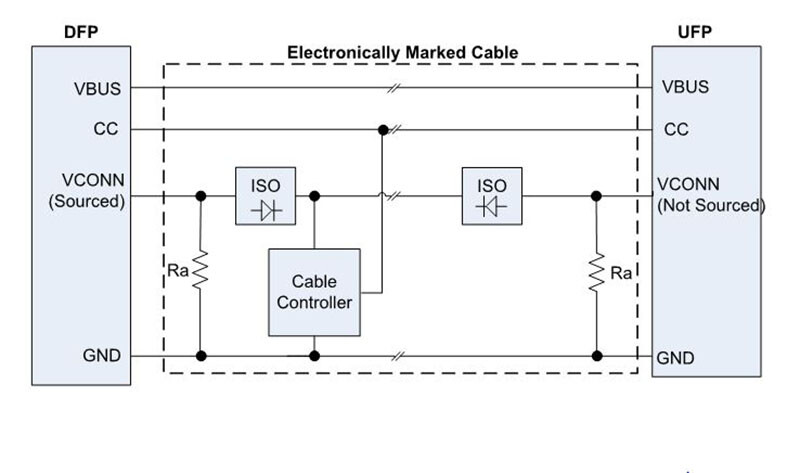
Some EMCA’s have a single marker chip on one of the paddle cards. Some EMCA’s will have two marker chips with one marker chip on each of the two paddle cards. If one marker chip is used, then a VCONN wire must be added to the cable that connects the two paddle cards. In addition, isolation must be provided on the paddle card to prevent both VCONN from being driven with voltage at the same time and colliding on the VCONN wire.
This matches what I previously understood about the standard.
Of course, not everything follows that standard perfectly
That said, there are non-standard cables that failed to run the VCONN line, and only have the e-marker on one side. Those will only charge at high speed in one orientation. Then there are the “integrated” cables that some USB-C hubs are using for the upstream-facing port (to the host): The company can shave a tiny cost by not requiring the e-marker on both sides (and not need the VCONN line run), when the upstream cable is manufactured into the hub.
If you want to get hints about the types of errors you’ll see in the real world, the Engineering Change Notice documents included in the USB PD specifications can be useful to read, as they inherently point out confusing text that products may have been built against (and thus have bugs around).
So far the e-marker has resisted my attempts to summons it.
It’s probably time to get a plank in development because it will take a few weeks to get the first revision prototype.
What I’m thinking:
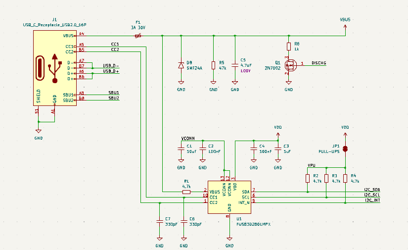
Reference design for FUSB302
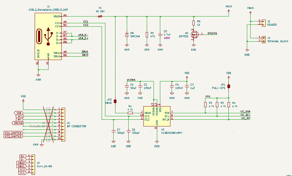
KF quick connect and screw terminal to access the power
All USB pins broken out
A fet from VOUT to VUSB for sourcing power when in source mode
The command to trigger different power profiles could go into main, but I also haven’t been able to query the profiles without a chip reset.
// PD message types
#define PD_MSG_TYPE_GET_SOURCE_CAP 0b111
bool fusb_send_get_source_cap() {
    /* Get_Source_Cap is a control message with no data objects */
    return fusb_send_msg(PD_MSG_TYPE_GET_SOURCE_CAP, 0, NULL, 0);
}
Sources reply to the command, but with 0 power profiles. From the specs I’m not sure what else I should be doing.
In summary: the basic functionality is there, but not enough for a really nice user experience. I’ll pause on the firmware for now and do some hardware for a bit.
They do! Although you’ll likely have no problems, note that the PD analyzer is a high-level analyzer, so you need to first attach the Manchester lower-level analyzer. In fact, here’s a post talking about just that thing!
Edit:
WARNING
Saleae might have trouble reading the CC line data…
The voltage differentials on the CC line are quite small, and determined by
the pull-up / pull-down resistors used for cable orientation and role detection.
If I estimate it correctly, it can range anywhere from 0.25V(!) to 1.6V when idle.
The controller then adjusts the voltage +/- 0.5V for the bi-phase mark encoding,
(presumably never dropping below 0V). If using a digital LA, maybe adjust the logic high/low trigger level to 1.0V? If dynamically adjustable, base the trigger on the idle voltage level?
Or, use an analog capture. But then I don’t think the LLA or HLAs in Saleae’s software get to see the data? May be that the Saleae is not the right tool for this job?
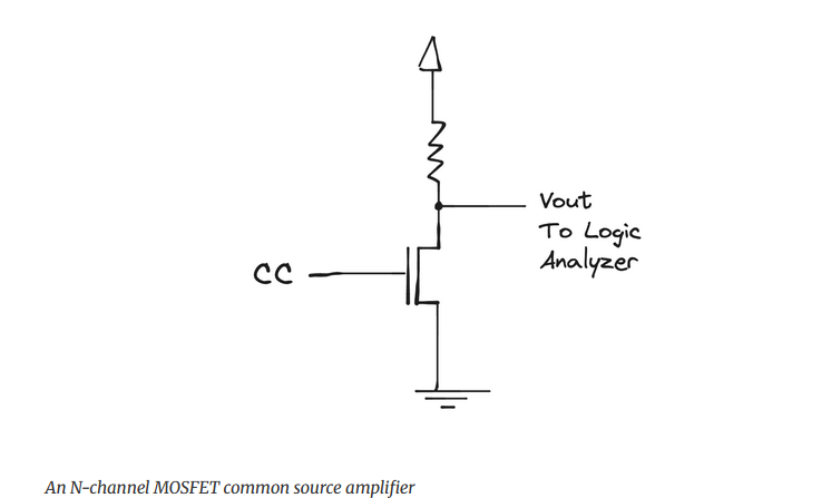
You are indeed correct. When Tom posted I found this post about using a cheap Saleae clone to read the CC line. They just used a FET with a pull-up resistor. We should probably add a FET or comparitor to both CC lines on the plank for easy debugging.
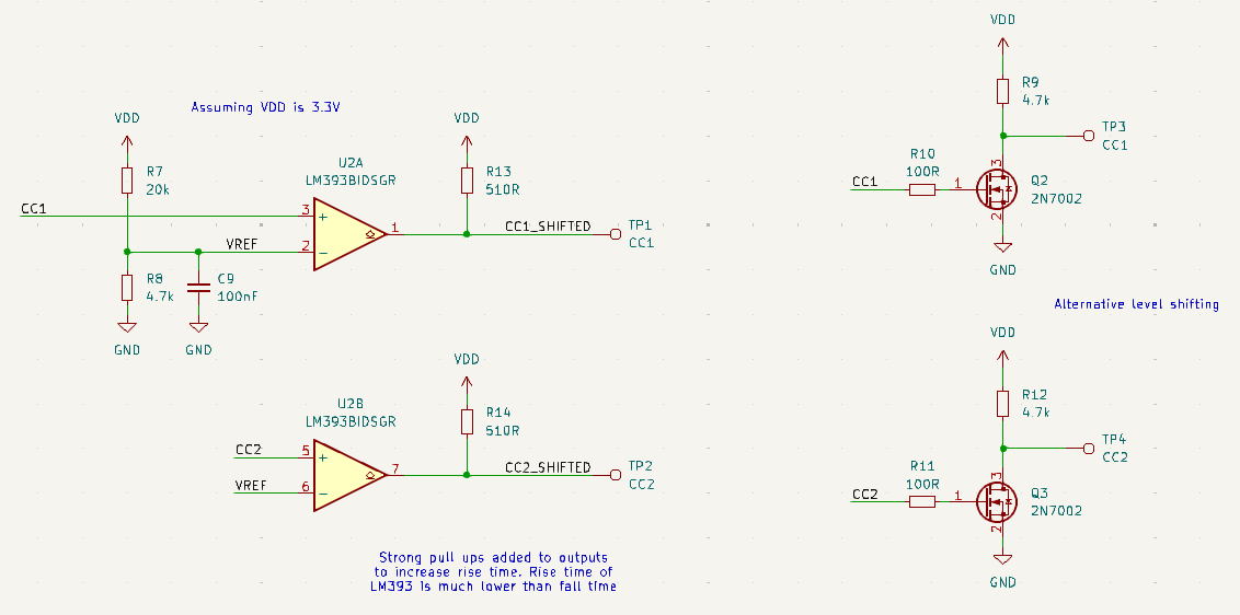
From the post linked above. Level shifting the CC output for a logic analyzer.
We’re starting the board schematic. For REV0 we’re going to try two level shifting methods:
A simple FET with pull-up as above
A comparitor with the threshold set at 0.4-0.7volts with a resistor divider.
I don’t plan to be a source at the moment. That would require VBUS be connected to VOUT, and in high voltage sink mode that would damage the Bus Pirate. We could include a physical jumper to cut that connection, but without a protection circuit protection the potential for damage to the Bus Pirate is very high. As we learned from the VOUT protection circuit (in progress), protecting a two-way supply from high voltages isn’t trivial.
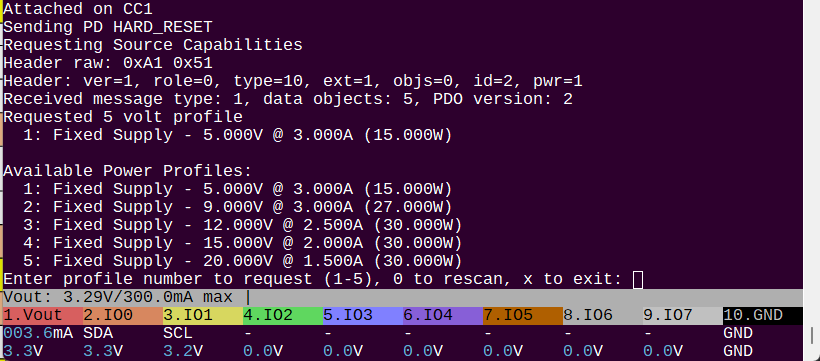
Now sends a PD HARD_RESET on attach for a clean start
Searches and requests the 5v profile immediately before the source times out
An interactive menu to select the power profiles, rescan, exit, etc
After 2-3 profile changes (depending on source) the source hard resets. The FUSB302 detects the hard reset error from my phone, but not from a USB charger. This is probably because we’re missing some stuff, and we’ll need a full USB PD stack to get much further. Or at the very least a logic analyzer connected for debugging.
I will clean this up and put it into main if anyone would like to try it or hack on it.
There are many hard timing requirements. Other projects that focused exclusively on USB PD failed just by adding logging, so it’s really not a surprise that it’s resetting … other projects setup a full state machine based on desired characteristics, which is … a lot to do!
I would love to see / get a REV0 if you have extra. Are you planning to keep the USB’s ground and VBUS separate from the BusPirate’s ground and VOUT?
Are you planning to have REV0 be designed to handle the full max power for PD3.1 ( e.g., 48V @ 5A), bringing VBUS and USB Ground to appropriately rated connectors (or at least unpopulated footprints)?
For example, would this require a heavier copper layer to get VBUS and the USB Ground to those footprints?
If it would require 2oz copper or similar, maybe add silkscreen text in the repo’s version of the files indicating the requirement for heavier copper. (and in your own boards, replace that with text indicating what power capacity it can handle.)
VOUT and VBUS will not be connected on this revision.
The FUSB302 has a upper limit of 20volts, 28 max. Though the Pinecile project found that many blow up over 20 volts. In theory we could not connect VBUS pin I think, since we are doing sink only in this revision (something the Pinecile project also did).
Yes, we’ll be sure to do heavy copper pours and calculate the max current.
I asked Supul to make a KiCad schematic for the FUSB302 breakout I bought as a starting point. I just received this and have not made my modifications yet.
Nice work Ian. Agree on all fronts, small steps, this will be fun. AFAIK 48V is optional in 3.1, we can do the long messages without 48V. I’m not sure the market is at 48V, I don’t see much on AliExpress yet. Personally I think once they hit 100W most use cases were covered (phones, laptops etc.). Perhaps once we see new fancy battery technologies we’ll see faster charging that will need 240W but for it to be useful to us it needs to be all over AliExpress. I still remember how hot a 100W light globe used to get, it’s a chunk of power.
WRT to level conversion, please also put a test point in for the raw pin. The real Saleae won’t need the level conv, it has ADCs. I’d encourage you to buy one (if you have the cash), they have generous discounts for hobbyists see Saleae Discounts
BTW I won’t need a board, I have the glasgow protos that I can strap to the BP for the FUSB chip. If there’s one sitting in the SZ office in December I’ll pick it up though - perhaps rev 0.2 by then. What I don’t have is much spare time, I’m on the road for work 5 weeks out of the next 12, each of those comes with the burden of catching up on lost office time. I love travel though, especially when it doesn’t come from my precious vacation budget. Thanks for the hard work.
It's true that the Saleae Logic / Logic Pro can capture analog, although that causes other analysis issues in `Logic 2`.
If I understand correctly, there are two downsides to analog capture using Saleae Logic for what is, in essence, intended to be a digital signal:
Protocol analyzers in Logic 2 only accept digital channels as input
The analog sample rate is slower (which may be OK, depending on application)
Because the analog channels are not even available for low level analyzers, there’s really no option to have an analyzer take an analog channel as input, and (via configurable thresholds) output a virtualized digital channel.
You might think this is something so obvious and trivial that it has already been asked for … and you’d be right. This was requested about five years ago… and the last comment (also 5 years ago) even mentioned USB PD decoding.
Unfortunately, I do not believe this has become possible between then and now.
Therefore, while I agree it’s a useful zero-cost addition to add a test pad (or even unpopulated through-hole) for the raw pin, I think you may find it less useful than you anticipate when using Logic 2.
Load them up … and try to follow along with what’s happening
For myself, I’m not a fan of the output format … and the data table is quite limited:
No filtering options … would like drop-down multi-select to filter items. JQuery UI data tables is more powerful here.
Clicking an entry does not cause the trace to show the relevant data of that entry. This appears to be inherent in the SDK API definitions, as they allow any key/value string pairs, and don’t reserve any method for common things such as the starting timestamp or duration, which could have automatic default actions (such as zooming to that area of the trace).
As a result, if I was using Logic 2, I’d like end up just exporting the data table to Excel or SQL, and then adding layers of logic above to see an even higher-level view of what’s going on.
Yesterday I spent a few hours browsing USB C power supplies on Taobao and Aliexpress. Here’s the vibes I caught:
Very few chargers include full specs for the PDO profiles available. I’ve heard this before and it probably makes even a simple source PDO profile reading plank a useful investigative tool.
Advertised power rating is almost always a sleight of hand: 100W is 1 x 65W capable port, 1x25 capable, 1x 10W capable A. If used in exactly the right configuration.
Of those where specs are available, most don’t go above 12volts.
Nothing I found on Taobao that advertised >20volts. This may be hidden or obscured by “compatible with” and “iPhone 16 charge time” comparisons, but they don’t list the specs so we don’t really know.
The USB charger we’ve been testing with has PPS with adjustable 3.3v to 11v @ 2.75A output. That must be the two 00 profiles that show occasionally. We’re not parsing those right, that is something fun we can look at this week.
Started pin assignments. VBUS is now connected to the FUSB302B via a solder jumper. Jumper can be removed when working with sources that can indeed provide >20volts.
The source we’ve been probing is “Shenzhen Good-she Technology” Model G5-W30A0963 Part number G40302. It’s been a great charger for a year or so now, at the time it was one of the most expensive on Taobao (which was the intention).