Will the FUSB302B work properly without VBUS attached?
When I looked at the datasheet, it shows the following:
VBUS input pin for attach and detach detection when operating as an upstream facing port (Device). Expected to be an OVP protected input.
This suggests two things:
If VBUS is not connected, it may not detect all the state transitions it needs to operate per spec
If VBUS is not protected to be <=28V (possibly actually 20V, possibly including ESD), else the chip may die
The datasheet also notes:
The FUSB302B also has a fixed comparator that monitors
if VBUS has reached a valid threshold or not. The DAC can
be used to measure VBUS up to 20 V which allows the
software to confirm that changes to the VBUS line have
occurred as expected based on PD or other communication
methods to change the charging level.
Based on the above note, I would be concerned that the chip would not function properly without VBUS attached (even when kept at low power).
Together with [Ralim], they figured out that the VBUS pin connection was not used in software at all, and in fact, could be completely disconnected. What followed was the “VBUS mod” – a hack would add 24 V support to the Pinecil by removing the VBUS connection, with video instructions on how to properly cut the trace involved.
[Ralim] modified the firmware to detect whether the mod has been performed correctly, as a failsafe for users who might’ve missed a sliver of copper the first time. The fix eventually made it into a new Pinecil PCB revision, too, and the Pinecil V2. Overall, it’s a wonderful short story of how large open-source products with a thriving community turn into a force multiplier.
According to the Pinecil project, there was an issue with exploding FUSB302s when using a 28V source. The solution was to remove the VUSB trace because it isn’t actually used in the Pinecil PD stack.
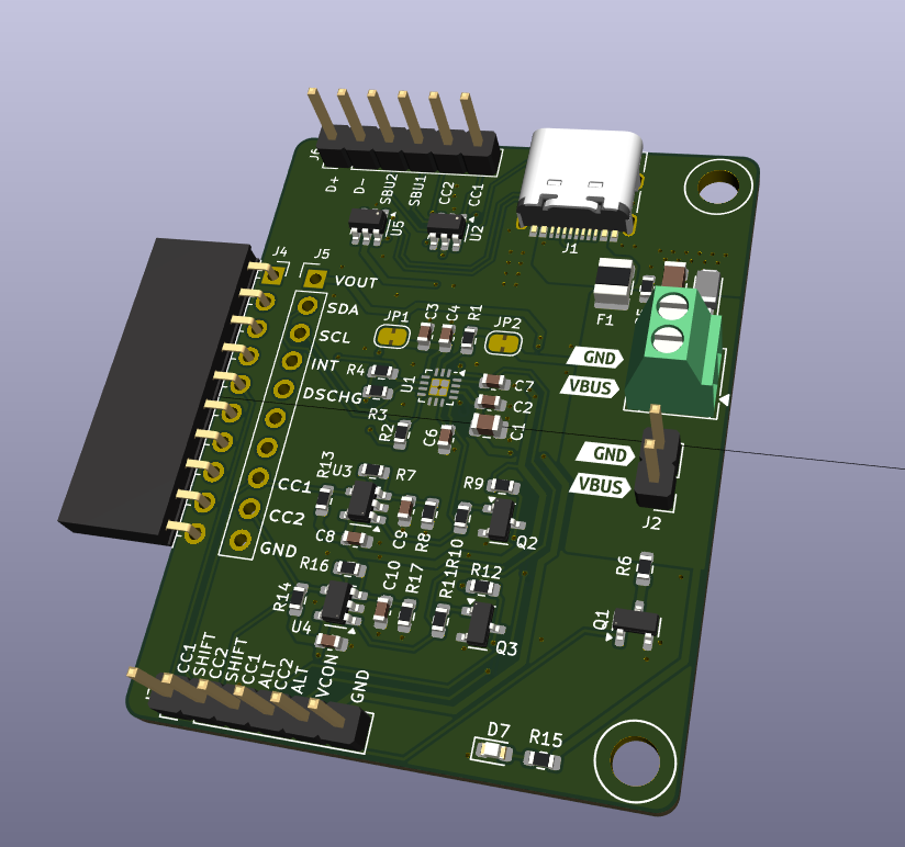
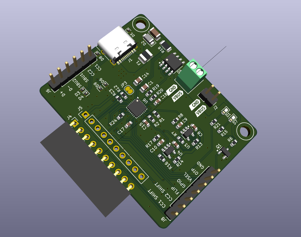
At the moment, this is also true for the Bus Pirate FUSB302 support. We measure CC1 and CC2 to detect attach, not VUSB. The FUSB302 has some automation to detect attach and source/sink status but the docs are pretty flimsy and every (open) stack and tutorial I’ve seen take the CC1/CC2 manual detect approach. That said, verifying the output voltage via VBUS seems like a handy feature. For the REV, I think a normally soldered VBUS jumper is a handy addition for testing.
I downloaded some saved logic traces and loaded them up in Saleae2 with USB PD and PD 3.1 analyzers. The USB PD analyzer doesn’t detect anything, while the PD3.1 analyzer works but is a bit meta as you described above.
Out of interest I’m going to try to decode the adjustable output PDO which is currently missing, and trigger it as well. That’s probably the last thing to do without adding a full PD stack.
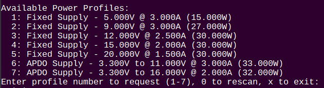
Move “Supply” to the header, e.g., “Available Power Supply Profiles”
Remove “Supply” from each PDO line
For APDOs, list type (SPR PPS/00b, SPR AVS/10b, EPR AVS/01b)
Reading through the USB PD specification, and I’m beginning to thing that an upstream-facing port (e.g., device) that is a power sink is not permitted to talk to the e-marker at all (not permitted to send SOP’).
Is that accurate, or am I missing the special timing when this would be allowable?
I have seen mention of it being possible in some posts, but not in the spec itself. I made a few attempts with VCONN powered, but couldn’t get any packets and didn’t try to be a source.
At the moment I’m just bashing at the phy, I think the REV0 plank will be a game changer because we can actually see whats happening on the wire.
I will make those display changes, but the whole thing is kind of in flux because we’re probably not escaping without some kind of mini-PD stack at minimum.
The short answer is that a power Sink is generally not permitted to send SOP' messages.
There is one exception
The exception requires both:
An Explicit Contract to be in place, and
The Source notifying the Sink that the Sink can initiate an Atomic Message Sequence.
Thus, the Sink not only needs to setup the explicit contract prior to trying to talk to the emarker, the Sink also needs to monitor the Source’s Rp value to detect when it can initiate communications on the CC line.
The specification explicitly forbids a device that is not supplying Vconn from sending SOP' packets.
Using USBPD Rev3 (v1.1) of the spec:
2.4.4 notes that coordination of the SOP* periods is required
When a Default Contract or Implicit Contract is in place (e.g., at startup, after a Power Role Swap or Fast Role Swap)
only the Source Port that is supplying Vconn is allowed to send Packets to a Cable Plug (SOP’) and is allowed to
respond to Packets from the Cable Plug (SOP’) with a GoodCRC Message in order to discover the Cable Plug’s
characteristics.
…
When an Explicit Contract is in place, only the Vconn Source (either the DFP or the UFP) can communicate with the Cable Plug(s) using SOP’ Packets/SOP’’ Packets
Sending SOP' messages outside the exception is likely to cause problems.
The Vconn source defines who transmits when.
If…
Other device is setup as DFP
DFP default is power Source
Plank is setup as a UFP (not dual-role capable)
UFP default is power Sink
Cable is attached to both the plank and other device
The plank sends SOP' packets
Then two issues…
The plank’s transmission could stomp on, or otherwise interfere with, transmission by other device (or the emarker’s response).
… but retries will typically hide this from upper levels
Other device is going to respond to the SOP' response packet with the GoodCRC Message
… and be processing a response to a message it didn’t send
… and who knows what that could do to that other device’s internal PD state machine
… exploitable? Likely could cause bad behaviors, at the very least.
Screwing up the other side’s state machine is the real risk. In a best case scenario, the other side might realize something is off (e.g., role switch it didn’t notice), and hard-reset itself.
So … yeah, this will require some finesse. Presumably if the FUSB* chip supports sending messages from a Sink, it does so only under the exception condition? Testing would be necessary to determine if this is true.
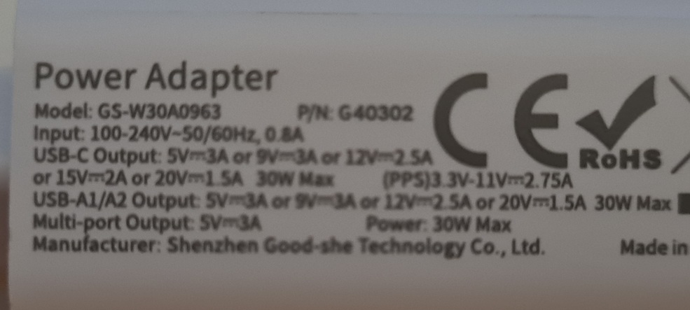
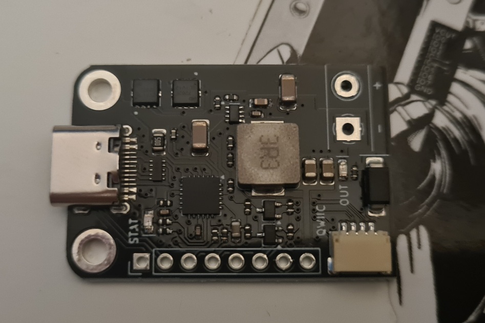
Supul alerted me to this chip when we were going over the FUSB302 PCB.
Sink only
PD stack is integrated, user only has to send simple commands to request profiles and status
Supports the current available full voltage range, PPS/SPR/EPR/AVS
it’s a basic “trigger” chip, instead of the dual role source/sink lower level FUSB302 PHY.
The bad thing is it abstracts away the USB PD to the extent it is useless for learning/debugging/sniffing, etc, and it is sink only.
The good things are
It replicates what I’ve managed to do so far with the FUSB302, without porting a full PD stack
Supports the higher 28v voltage node properly (more modern)
Safety features
Could be in the store much faster
We’re doing a second USB PD board with this chip. It’s not a replacement for the FUSB302 board, as it can’t do a fraction of the same stuff. But, it is a fast and easy way to probe and select PDO profiles and get some basic status information.
The good news is the AP33772SDKZ breakout arrived. A library to support it is already in the firmware, so I’ll proceed with testing.
The bad news is that there seem to be no AP33772SDKZ available in the market. We can’t even get 2 chips for the proto run, and SZLCSC says 60+ days back order. We may try to import some, but that is a whole thing.
SZLCSC actually lists foreign distributors, so I assume they will do the importing but not sure about the quantity. One of our part scalpers offered to import them at not a terrible cost, they may just be using SZLCSC though. It’s Friday though, and we ran out of time to follow up on the import stuff.
While the I2C docs seem quite standard about continuing to read multiple bytes, you can in fact only read one register at a time
While the I2C docs say a I2C RESTART is ok, in reality the device seems to hang on the line without a full STOP and START. Verified this with a LA, and also tried other devices to make sure it isn’t a Bus Pirate problem
The device is powered by the USB source, so it is not interactive until a source is actually connected
The current from the pull-up resistors, powered externally at 3.3volts, is enough to keep the device from resetting when the USB source is removed. It will not respond to I2C in this state, so a hard reset command is not possible. The pull-ups have to be disabled before the device resets and detects the next source insertion.
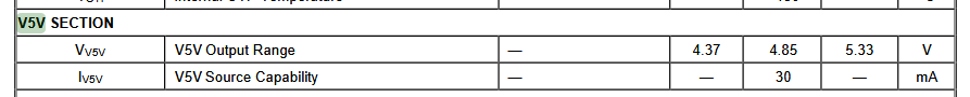
Everything is reasonable, except the final point. On this breakout board there is a 5volt step down converter so that 5v is always available. If I power the Bus pirate pull-ups and pins from this external supply, when a source is removed the pull-ups are also powered down and everything comes to life on the next insertion.
This is from the Diode’s INC dev board. So it seems this is an issue.
However there is an on-chip 5volt LDO, we could use that for the pull-ups and the supply would disable when the USB source is removed. One possible solution.
This is really cryptic and I couldn’t find anything else about it: When VCC is off, V5V pin could be an alternative power path for the AP33772S when provided a 5V external power.
That sounds like what we want to keep it alive at all times. I assume we’ll need some kind of circuit that disables the external supply when VCC is on, but that seems tricky to time right to avoid losing configuration settings. I will look for more info about this pin.