BP7 REV0 proto run

All the usual caveats: this is not hardware, it is a discussion. This revision (REV0) has already been superseded by REV1.

Feeling a bit burned out on the OTP stuff, so I want to dedicate a day to hardware. PCBs and solder stencil are being made, but the updated BOM still needs to be sourced.

7-REV0.zip (8.7 KB)

New/changed components are in yellow.

Quantity Reference Value Footprint
1 C21 10uF 0402
2 C6, C13 10uF 0805
9 D1, D2, D3, D4, D5, D6, D7, D8, D9 BAS40-04 SOT-523
1 R10 470K 0402
2 RN4, RN7 4.7K Array_Convex_4x0402
2 RN5, RN6 2.2K Array_Convex_4x0402
1 U105 MT29F2G01ABAFDWB (2gbit?) U-PDFN-8
2 U4, U5 MCP4725A0T-E/CH SOT-23-6
2 U6, U7 TCA6416ARTWR* Ask scalper qfn24-4x4x50:QFN50P400X400X80-25N
1 U8 APS6404L-3SQR-ZR* Ask scapler USON-8-1EP_3x2mm_P0.5mm_EP0.2x1.6mm
5 U9, U10, U11, U12, U13 LM(V?)358* Ask Gainsil for samples DFN-8-1EP_2x2mm_P0.5mm_EP1.05x1.75mm
1 Like

So this is to get used to the I2C-DAC and advanced pull up/down capability, but does not include changes to the ADC and not the advanced protection things, correct?

How about the PSRAM?

I generally like this gradual approach, doesn’t require as much firmware changes in each revision.

Do you see any issues in changing the pin assignments again for the next iterations of Rev7? Like too many if sections in the code to get all of these handled.

1 Like

Here are the REV0 updates:

  • Move RBG CDO up to the 0…32 range so we can use the extra PIO on the buffered Io pins.
  • uses I2C DAC to set voltage and current levels instead of PWM (claim 2 pins)
  • adds I2C IO expanders for 4 possible values of pull up or pull down (and combinations) assignable per pin
  • Add 8MB (?) PSRAM that can be memory mapped for a luxury logic analyzer.
  • DFN opamps and other tweaks for space and manufacturability.
  • A small circuit to allow the bootloader button to be reset or bootloader depending on press length

Coincidentally, someone has already gotten the PSRAM working.

I fully expect this to be a quickly discarded REV. I would have built it ages ago, but we couldn’t get the RP2350Bs in the market until a few weeks ago (and then it was Spring Festival holiday).

I have no problem making drastic code or pin changes between REVs, in fact I relish it :slight_smile:

2 Likes

@ian you mentioned several times that the planned Rev7 stuff will be much more expensive than Rev6 (and Rev5 even more).

I’ve been working on preparing the pull request for the port protection stuff, but with this cost-thing you awakened a brainworm in me that constantly looks for things to cost-optimize…

You mentioned that especially the new I2C DACs are expensive, but I don’t have any actual volume prices at hand.

Would it save BOM costs to use one more I2C IO-expander TCA6416RTWT and move several of the slow 3.3V-IOs over to them? That would free IOs on the RP2350 and we could go back to the original PWM solution.

Or maybe use a smaller, not so sophisticated I2C IO expander?

Slow IOs would be things like CURRENT_EN, CURRENT_EN_OVERRIDE, CURRENT_RESET, BUTTON, DISPLAY_RESET, Activate_VOUT.

To not need constant polling, we could use the INT output of the TCA6416RTWT.

2 Likes

While doing the port protection schematics changes I noticed some changes that could also make sense to already include in BP7 Rev0:

  • change the USB termination resistors to the 27R recommended by RapPi
  • change the GIGANTIC SOT-23 MMBT7002K fets to more appropriate SOT-523
  • you already have a lot of 4.7µF caps in 0402. My default instead is 10µF in 0402 (Samsung CL05A106MQ5NUNC / C15525). So when you copied my reset/bootloader circuit you added one more BOM line. I think this isn’t necessary. So I suggest to change it to 4.7µF / 560k instead. The values have to be tested with your capacitors because voltage derating plays a big factor here. The 560k are eyeballed, we could use this revision to fine-tune.

I implemented all of the changes above in my pull request for the port protection stuff, so you could copy from there.

Alternatives:

  • An alternative could of course be that you change all your 4.7µF caps to CL05A106MQ5NUNC. They will probably have more capacitance left at the target voltage, but depends on actual part no you use.
  • You also have some 2.2µF caps in 0402. I don’t know what the point of these is in comparison to also using 4.7µF or 10µF.
  • I now use the 10µF everywhere I have used 100nF for decoupling in the past and the voltage isn’t too high (<= 5V).
1 Like

There are some gotchas in there. We still need prices from the scalpers (less than reel sellers for parts that do some volume). SZLCSC isn’t predictable of cost, but hints at availability. Let’s see what happens when we get actual quotes tomorrow. It’s a bit ambiguous until @jin does his thing.

The Xinluda XL9555QF24 could work in this role:

1 Like

I think these are all good suggestions.

Still need to see real prices, because they often surprise, but I think an extra IO expander will cost more than the two DACs. I also like that the DACs are right where they need to be. In BP5/6 we run the snubbed PWM signal all the way across the board.

Interesting, now I want to spend the day sourcing alternatives :slight_smile: For the (unknown as of yet) price difference, I’d rather have it work over the 5-1.65v range than the 5-2.3v range of the cheaper chip. That chip would be a good candidate for moving more output signals off the RP2350 though.

I’ll review the push and merge now, thank you so much.

1 Like

The XL9555QF24 can only work as a IO expander to move slow signals off the RP2350.

It won’t work as alternative for the TCA6416RTWT for the pulls. The reason is that it just has one voltage supply. The TCA6416RTWT have two voltage levels, one for the I2C-bus (3.3V in our case) and another one for the io-pins (VREF_VOUT in our case).

1 Like

Yes, the DACs are nice. But they don’t really add a new feature or capability, so if they were really expensive, I’d try to find a replacement. Let’s see what the real prices are.

Another thing to optimize: you currently have TCA6416RTWT planned in the schematics. But there are newer TCA6416ARTWR available that would work as well and could be cheaper. So make sure to check both.

There are also TCAL6416, but they won’t work because they don’t support 5V.

1 Like

FWIW, I just read that the RP2040 has been certified to run at 200Mhz in the SDK 2.1.1 release notes

3 Likes

Good catch! I remember this from months ago when we were doing the design, but it had slipped my mind. I updated the BOM above and let jin know. The other seems obsolete, so I assume the scalper would have directed to the newer part eventually. Great to know now though because we have something to speculate against :slight_smile:

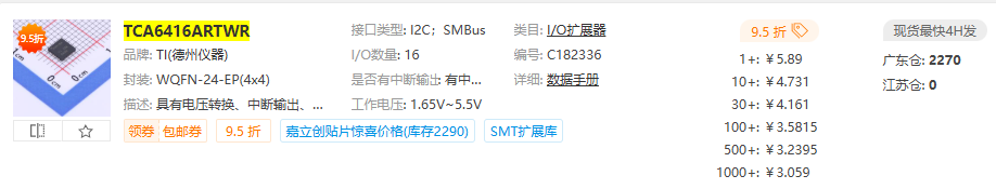
For an initial batch of 100 (200 pcs IC) it adds ~7kuai + 48 pins * 0.01USD = around $1.50 raw cost with no overhead (wastage, shipping parts around, the folks who do all that for us, international payment overhead). In practice this probably adds $5 to the wholesale cost, and mark that up another 30% for retailers and we’ve added ~$7.

The scalpers may offer us ~2kuai each, but that is only a guess. I checked 1688/taobao/tmall and this isn’t common enough to guess a price.

It is, to me, a pretty steep price increase for something with a base price of $40 (BP5). Is it worth it? For me absolutely, it’s cool and I want to do it. Clearly it has some value to you for dedicating your time and skills to getting it going :slight_smile: I think for people who see the need for this (cable testing, blind pin probing) it is probably a real bargain.

Will 95% of people get along just fine with a single 10K pull-up, yes probably also true :slight_smile: And they will be sure to let me know on social media :slight_smile:

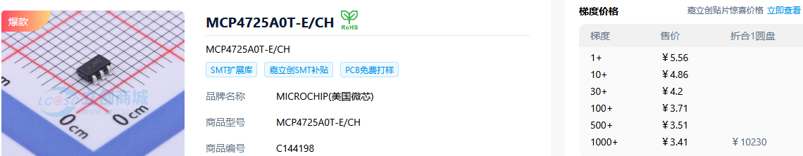
Same deal here, about the same added cost. However this one is much more common and I would guess we might get it as low as ~1rmb.

I don’t mind the added cost, I’m not trying to debate or second guess any aspect of the current design at this juncture. I’m very happy with it. At this phase I’m not concerned about optimizing for cost before we’ve even dog-fooded the first REV and decide if we like it.

I am very wary of giving people the wrong impression that this high end board using brand name parts will come in at about the same price as the BP5. It just isn’t possible, and I suppose I feel a little defensive about that so I try to tamp down expectations.

We have a workhorse base model Bus Pirate that is hyper optimized for cost because it was designed for the supply chain crisis era. My gut instinct is that the project is best served long term by having tiers of incrementally more expensive and complicated boards like the 6 and 7, rather than trying to cram all the features of X into the same price point as the 5.

That got a bit out of control, sorry for the wall of text. I wanted to clarify my feelings on price points, I fear I gave the impression I thought things were getting too expensive.

Unfortunately jin is out sick and didn’t get quotes today, hopefully tomorrow.

1 Like

Moved to here:

Is this something you already would include into the first BP7 Rev0 run, the one without the port protection stuff? Or is this for BP7 Rev1 with port protection?

We already have a 10uF 0805 cap somewhere else. And we need a 10uF 0805 cap for the 9V aux rail.

But these are much larger than 0402, so I would just use them where they are really necessary because of their size. For example the reset/bootloader thing will work fine with a 0402 cap, once you paired it with a matching resistor.

So I would go for one large capacity one in 0402 and one 10µF 0805.

Which exact part number are you currently using for 4.7µF in 0402?

This is all for the port protection stuff, so BP7 Rev1 and not Rev0, right? I’m now a bit confused about what goes where.

1 Like

Moved here:

Manually moved post to the correct thread.

As in PCBs ordered and in production while the parts are not ordered yet, right?

Otherwise you’d already have the prices for TCA6416RTWT/TCA6416ARTWR and the DACs.

So layout changes aren’t possible anymore, but swapping part numbers with the same footprint would still be possible, right?

1 Like

Correct! It is in @jin’s hands now. PCBs are in production, stencil is made.

We can swap part number/values if the physical layout doesn’t change. At least until Ru starts the assembly part kit. I would guess Monday.

1 Like

You then have a 10µF CL05A106MQ5NUN planned for the reset/bootloader circuit, together with 470k?

Did you incorporate my change of the 22R → 27R resistors for usb termination?

1 Like

Your update of the terminating resistor is already in the BP7R0 BOM.

Updates pushed:

  • All 2.2uF, 4.7uF → 10uF/6.3V CL05A106MQ5NUN
1 Like