Todo:
Set R208 (LCD backlight FET gate resistor) to 0 Ohms.
Todo:
Set R208 (LCD backlight FET gate resistor) to 0 Ohms.
| Part Number | Quantity | Unit Price | Full Reel (3K) | Reel Unit Price |
|---|---|---|---|---|
| TCA6416ARTWR | 200 | 2.3元 | 3K | 2.1元 |
| MCP4725A0T-E/CH | 200 | 3.3元 | 3K | 3.1元 |
| APS6404L-3SQR-ZR | 100 | 7.5元 | 3K | 6.8元 |
The TCA chip is quite a bit cheaper than I expected, but the DAC is still pricey.
The APS chip is the 8MB PSRAM, I guess the price is fine. I’ve heard rumors of a 16MB model being released, but that is for a future REV.
Thanks for posting the prices.
So if the layout permits it, we could replace the 2 DACs with PWM again and move some slow IOs to a XL9555QF24. This could save about 4 or 5 yuan.
But let’s keep the DACs until we are happy with the overall concept and design and move to a cost-optimizing phase.
Maybe a future concept can work in a way where you have one common design for the cheap and full versions and the cheap versions just have some expensive parts not populated, like the PSRAM or just two pullup/pulldown resistor values instead of 4 (would have to adapt the layout for that though).
I like the idea of being able to incrementally add optional functionality to a base design. A user could buy the core Bus Pirate model (that has ALL of the options already designed into the PCB) and then populate the PCB with the required parts for any upgrades as and when they can afford it.
One thing I noted while reading the discussion about the PSRAM in the other thread:
Is the pullup for the PSRAM chip select with 100kOhms (R6) strong enough?
The RP2350 by default enables it’s pulldowns on all IOs during boot. It doesn’t know that the GPIO47 is a chip select where the data could interfere with the QSPI of the NOR flash.
So the internal pulldown (something like 30 to 50k IIRC) would create a voltage divider with the 100k and I’m not sure if this will work reliably.
So I suggest to use 10k instead to be sure that it overpowers the pulldown.
Or do I miss something here?
I reviewed several RP2350 dev boards with PSRAM and cribbed the value they used. It shouldn’t hurt to be 10K, so I updated REV0 and REV1.
BOM for REV0 will be locked in tomorrow, so please let me know if anyone has any final changes.
BOM is locked. Sourcing will start tomorrow AM China time.
PCBs done. Assembly is scheduled for end of this week. Engineering samples will probably mail out Tuesday of next week.
BOM sourced and assembly is awaiting our part kit.
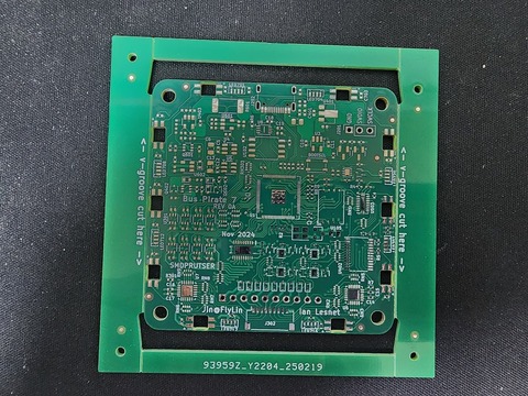
“Nov 2024” ![]()
I see that I’ve still not convinced you of the evil of the LEDs facing the same side as the screen. Is there time to update REV1 or REV2 to have all side-facing LEDs?
I haven’t forgotten. When the design/BOM stabilizes I will do a variant with all side facing LEDs.
Part of the issue is that BP5 is basically in constant production now. We store our reels in the climate chamber at the volume assembly factory instead of returning them to the office.
That makes part kits a time sink because we order everything for 2 or 4 engineering sample runs, instead of cutting from/sending reels to the prototype factory.
For the REV0 part kit I suggested @jin buy full reels of the cheap parts (resistors, mostly) so we have them. He doesn’t trust us not to change a bunch of stuff and instead ordered cut tape from SZLCSC.
When the design stabilizes we will get full reels of everything under 300rmb/reel. Then we will be able to rapid fire some variants without disrupting the normal flow of the office too much.
Thanks for still considering it. At least if the change to all side-emitting pixels is done, it wouldn’t add new parts to the BOM … and would in fact remove one part (the through-board pixel).
Since the through-board take space on both sides of the PCB, I thought it might even open up some board space… But then I looked and noticed only one side has surface-mounted parts (presuming button and screen added afterwards). Yeah… I know I’m a noob at PCB design.
Am I deducing correctly that it’s not (easy/cheap) to do surface-mounted parts on both sides? (It would make sense … how to keep the first side’s parts from falling off while reflowing the other side?)
Might be obvious once you look into it, but … I honestly never really thought about it before. ![]()
I’ve never done a two sided board, but it is definitely possible. There is a solder paste stencil like process using “red glue” that holds the upside down parts on the board.
Interesting. More expensive? More failures? Must be some reason it’s not as common… do you have any hints / rumors / knowledge there?
If it’s a solid process with minimal yield / cost impacts, then … I just found you a ton of extra routable board space. ![]()
And there might be even more with the move to all side-emitting pixels, since the holes would be gone (and thus routable space). ![]()
Then again, it probably is higher cost, and probably does impact how many boards need rework, so … maybe not worth it?
[[Must … resist … urge … to dig into PCB files …]]
Curiosity is a dual-edged blade…
In the past I’ve been told it costs twice as much to assemble. That makes sense.
In our case, there isn’t that much to be gained. The LCD covers most of the other side and the case would have to be redone to accommodate the second side components.
I just want to chime in here with the idea of moving the NOR-flash and PSRAM to the top side to save space for rev 8:
Doing this with a double sided pcb would of course be easier.
Generally populating both sides is more complicated. You need a jig or standoff to hold the pcb when printing solderpaste through the stencil for the second side. And the other issue is that bigger components from the first side could fall off when soldering the second side.
Small components like ceramic caps and resistors will hold on by surface tension of the molten solder. QFN parts with exposed pad often too. But there is a weight/solder area ratio where parts will begin to fall off and have to be glued down with a special glue before. Printing this glue is an extra step. Also it makes rework hard to impossible.
You and Henry have both mentioned going some form of two sided. I’m not against it, though I don’t have much to contribute to that discussion at the moment. I have no problem using “red glue” to do 2 sided assembly, but have not done so in the past.
Here are the main questions I have:
Did some major cleanup to prepare for 7REV0:
#define BP_HW_RGB_HAS_ALL_PIXELS !(BP_VER==5 && BP_REV<=9) at the top of rgb.c, instead of specifying the in each individual switchI will make an attempt to do a search and replace of BP_VER and BP_REV to be less confusing, but last time we tried it caused unknown problems and had to revert.
Version 7 firmware compiles, but I have yet to add code to support the new pull-x system or the I2C DACs.
My motivation was to get a bit more board space to fit the Vout-protection in Rev8. This could also be solved differently, like when the new ADC would allow to leave out the opamps. Also you’d have to calculate if moving the ICs to a small extra board with castellations is cheaper than a whole double sided production.
Using side leds on top will only work with double-sided.
I don’t really care about the way the LEDs face and for me such looks things aren’t that important. But that is probably just me, other people tend to care more about looks. Also I can’t say if side leds will look better than it is now without having them both lit up next to each other.
I guess for both variants some changes to the case would be necessary. This would add more clearance, so material from the tooling would have to be removed - which is much easier to do than adding some. If designed properly it should be possible to do it in a way that it works for both Rev5 and Rev>=8.