I requested some more info on two sided assembly, will share when I know more.
1 Like
Enclosure impacts...
Wow, I hadn’t realized the case was quite so form-fit on the top. I was unable to add a 1.5mm thick pcb piece lying flat near the button, for example. I had (wrongly) presumed there was space in the case … that definitely tips the scales against using the top side.
On the plus side, I verified the new case should have no trouble with the pixels being moved to fully side-emitting versions. The case bottom is a nice open formless void. ![]()
Enough board space to justify...
If the holes for the through-PCB pixels are removed, that may tips the scales slightly.
As for being “enough to justify” a move to 2-sided: The move to 2-sided was only floated because I heard the space constraints affecting design decisions. Moving to 2-sided (in my view) should be a forced move … not something to be done unless it’s actually needed.
That said, if the space constraints continue to be problematic, it’s good to have had this discussion. If we didn’t even know what potential costs / benefits existed, then it would be much harder to evaluate options. Just knowing it’s possible may also help with mental health, if space becomes unbearable. ![]()
TLDR Summary:
- Move to 2-sided should be based on need … not for fun.
- Understanding the costs/risks is beneficial, even if not something done in the near future.
- Usable space is in four quadrants near the corners
- Two fairly small areas on the connector side
- One larger area on the USB side, essentially cut in half by USB through-hole pins and button.
- Consider updating case to allow space for surface-mount components on top? (presume through-pcb pixel holes are gone for planning purposes … keep selling current case stock)
- Logos may need to get smaller (e.g., verify regulations allow it, look for creative placement, such as FCC overlap with screw hole, etc.)
2 Likes
Pushed some firmware updates for REV0:
- Merged updated version/revision handling into main
- Added support for I2C DAC (psu) and IO expanders (pull-x) on bp7r0 branch (experimental, for basic testing/verification)
1 Like
[build] [ 67%] Linking CXX executable bus_pirate7.elf
[build] Memory region Used Size Region Size %age Used
[build] FLASH: 729928 B 16 MB 4.35%
[build] RAM: 251932 B 512 KB 48.05%
[build] SCRATCH_X: 4 KB 4 KB 100.00%
[build] SCRATCH_Y: 0 B 4 KB 0.00%
[build] PSRAM: 0 B 8 MB 0.00%
Attempting to add support for the PSRAM. It’s showing up.
MEMORY
{
    FLASH(rx) : ORIGIN = 0x10000000, LENGTH = 16384k
    RAM(rwx) : ORIGIN =  0x20000000, LENGTH = 512k
    SCRATCH_X(rwx) : ORIGIN = 0x20080000, LENGTH = 4k
    SCRATCH_Y(rwx) : ORIGIN = 0x20081000, LENGTH = 4k
    PSRAM(rwx) : ORIGIN = 0x11000000, LENGTH = (8 * 1024 * 1024)
}
Added 8MB of PSRAM to the linker file.
    .flash_end : {
        KEEP(*(.embedded_end_block*))
        PROVIDE(__flash_binary_end = .);
    } > FLASH =0xaa

    .psram (NOLOAD): {
        . = ALIGN(4);
        *(.psram*)
    } > PSRAM
Added a PSRAM section to the linker file.
2 Likes
I2C> P
Pull resistor: 10K, Direction: UP
I2C> P 2.2k
Pull resistor: 2.2K, Direction: UP
I2C> P 2.2k -d
Pull resistor: 2.2K, Direction: DOWN
I2C> P 4.7k -d
Pull resistor: 4.7K, Direction: DOWN
I2C> P 10k
Pull resistor: 10K, Direction: UP
I2C> P 1m -d
Pull resistor: 1M, Direction: DOWN
I2C> P 2K
Invalid resistor value:
 Valid values are 2.2K, 4.7K, 10K, 1M, OFF
I2C> P off
Pull resistor: OFF
A rough prototype of the new pullx command. It does not currently support per-pin assignment, I need to figure out how to do that.
- P - with no arguments defaults to 10K pull-up
- P 2.2k - with a resistor value (case insensitive) enables pull-up
- P 2.2k -d - the -d flag sets pull-down instead
- P off - (counterintuitive at the moment) completely disables all pullx resistors
- p - disable everything, enable 1M pull-down on all pins
I2C> P 2.2k -p 1 2 3 4
Pins: 1
Unfortunately the command line string parsing function stops at space. We will need a variant that parses to the next ‘-’ or end of input.
I2C> P 2.2k -p 13457
Pins: 1 3 4 5 7 Pull resistor: 2.2K, Direction: UP
A work around hack for testing could be to enter then without spaces…
Or, perhaps another way to handle per-pin assignments.
1 Like
I think the whole command line interpretation and how commands get defined could use a facelift.
I found the following library… it seems REALLY promising.
Should I dig deeper? It could be an amazing upgrade to the user experience…
[Edit – updated to proper (recent) version]
2 Likes
There are other command line interfaces as well. I last looked at one with auto suggest while typing and a bunch of other cool stuff. As long as we don’t end up glued to a strange restrictive interface I don’t mind an upgrade, but whatever is used will need to play well with the syntax compiler.
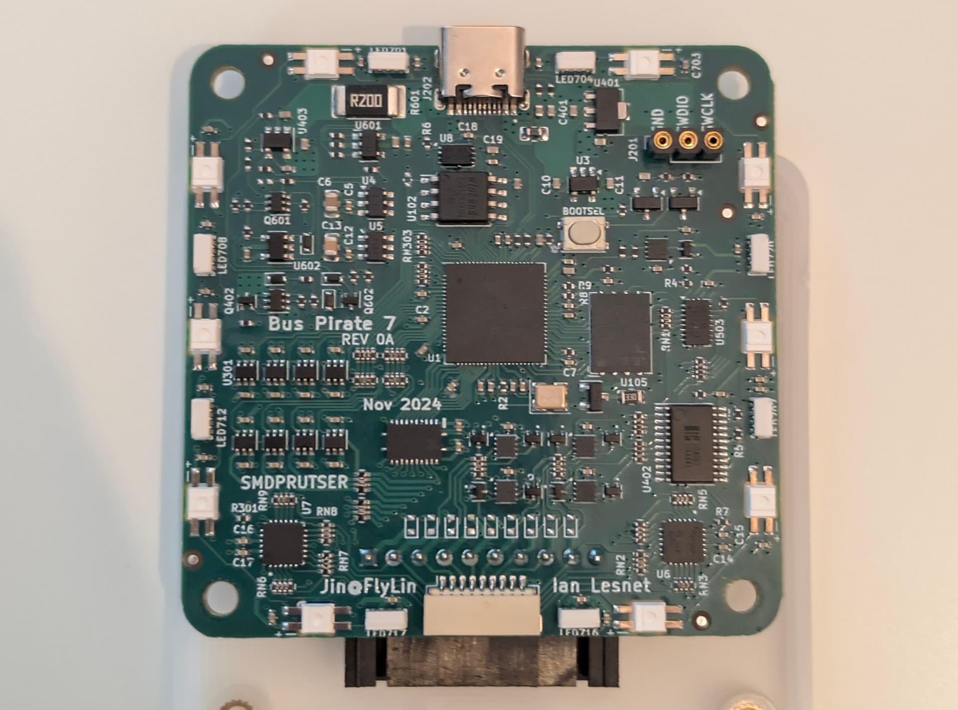
REV0 was assembled today. We should be able to mail out the engineering samples on Monday.
4 Likes
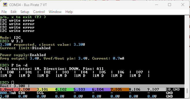
I2C> P 2.2k -d
Pull resistor: 2.2K, Direction: DOWN, Pins: All
Configuration:1111111111110000 1111111111110000
Output:0000000000000000 0000000000000000

I2C> P 10K
Pull resistor: 10K, Direction: UP, Pins: All
Configuration:0000111111111111 0000111111111111
Output:1111000000000000 1111000000000000

I2C> P 1m
Pull resistor: 1M, Direction: UP, Pins: All
Configuration:1111000011111111 1111000011111111
Output:0000111100000000 0000111100000000

I2C> P 10K -p 0246
Pull resistor: 10K, Direction: UP, Pins: 0 2 4 6
Configuration:0101111111111111 0101111111111111
Output:1010000000000000 1010000000000000

I2C>
Individual pin resistor and up/down now stored in the system_config struct. There is also a function to convert the stored settings into the actual data that is sent to the IO expander.
I2C> P 1k
Invalid resistor value, valid values are:
OFF 1.3K 1.5K 1.8K 2.2K 3.2K 4.7K 10K 1M
I2C> P 1.3k
Pull resistor: 1.3K, Direction: UP, Pins: All
Configuration:0000111100000000 0000111100000000
Output:1111000011111111 1111000011111111
Resistors can be combined for several extra values.
Next I need to add some kind of status indicator to the P command and the i (info) command.
EDIT:
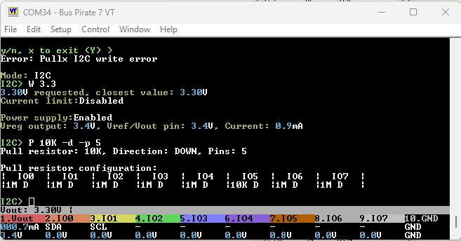
I2C> P 2.2k -d -p 0123
Pull resistor: 2.2K, Direction: DOWN, Pins: 0 1 2 3
Configuration:1111111111110000 1111111111111111
Output:0000000000000000 0000000000000000
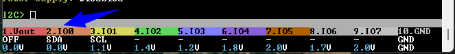
| IO0 | IO1 | IO2 | IO3 | IO4 | IO5 | IO6 | IO7 |
|2.2K D |2.2K D |2.2K D |2.2K D |OFF |OFF |OFF |OFF |
I2C>
Rough display of current pin pullx state.
1 Like
Pushed what I think will be the final pullx command (at least until we can actually test).
I’m going to be bold and merge into main. It should be safely cordoned off from the other hardware versions.
More boldness to come: it makes sense to add the XL9555 drivers for 7rev2 since it is essentially the same code and I’ve carved out a place for it.
3 Likes
7REV0 arrived to the office. Boards shipped to @phdussud & @henrygab. Awaiting confirmation from @electronic_eel.
@henrygab we located the certification samples with the blank OTP, and you will receive one.
3 Likes
Excellent! Looking forward to playing with it.
2 Likes
Merged 7R0 updates to main. This includes a complete rework of the way features are added/removed for various hardware versions. The pullx resistors and I2C DACs (for the PSU) should also be supported.
Currently the 7R0 build is commented out in cmakelists so the autobuild doesn’t compile it. Uncomment and it should “just work”.
3 Likes
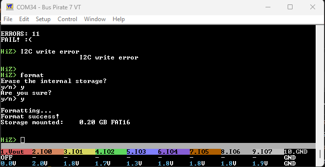
Bring-up:
- Display, LCD, LEDs appear to work
- 2Gbit NAND format success
- Bootloader button: short press reset, long press bootloader (long press a bit unreliable at times, or maybe I don’t have the hang of this yet)
- Because the pullx chip is reset until VOUT is powered, there is really bad leakage through the op-amp protection diodes. It goes away when touched with a multi-meter. We may have to add back a permanent 1M pull down.
- Fixed firmware bug where all pullx resistors display as up, even when down.
- Updated platform file to match new AMUX connections
- Fix bug: PICO I2C write command expects 7 bit address (grrrr, training wheels)
- PSU DACs now working, but there is a small calculation error:
– ~0.1v too high
– >=4.9 volts wraps around to 0.8volts.
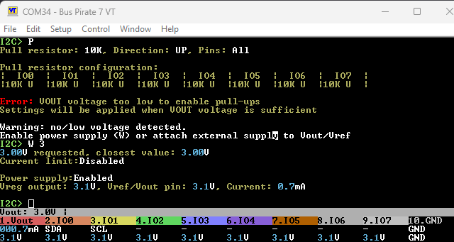
- pull-x IO expanders are working. Need to tweak behavior:
– if vout <1.65, show warning: too low, chip not active
– When PSU is activated/changed refresh the pullx values
– When VREF (external) voltage > 1.65 refresh the pullx values
– ? - pullx doesn’t seem to be able to pull high, investigating
- Fixed some nasty bugs in the processing the pullx selections to actual pin on the IO expanders. Seems to be good now. All values tested with a multimeter on all pins
- Pullx writes and then read/verifies the values in the IO expander registers. Failure to ACK or verify would indicate the IO expanders are not powered (or not working…). This will be used to handle reconfiguration after power is cycled.
- Pullx: removed debug, clean up info display
- Pullx is working but needs some polish (next post)
1 Like
Pullx To-do:
- Handle errors during startup when IO expander isn’t powered
- Handle errors during mode change when IO expander isn’t powered
- Reconfigure pullx after any W/w power change, handle errors gracefully
- Detect power change on VREF and reconfigure pullx
Could be that you use different FETs than me or something like this. You could try to reduce the 470k resistor to shorten the time required for long press.
But I can also play with this once I got mine.
Multimeters often have 10M impedance (unless you got one of the better benchtop ones that got Gigaohms impedance in the lower ranges).
This hints that a permanent 10M pulldown could help to solve this. But also see my post in the other thread 7REV1+ ideas SPI ADC, IO expander, roadmap - #70 by electronic_eel
1 Like
Let’s see what you think of the boot reset when it arrives.
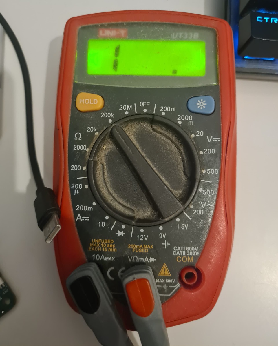
Someone left this behind in my first Shenzhen office. I upgraded the probes at one point. Betsy is reliable, but doubtful we are looking at gigaohms here ![]()
1 Like
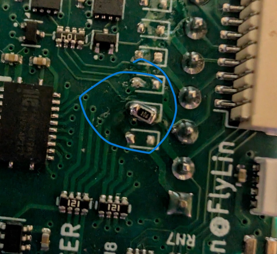
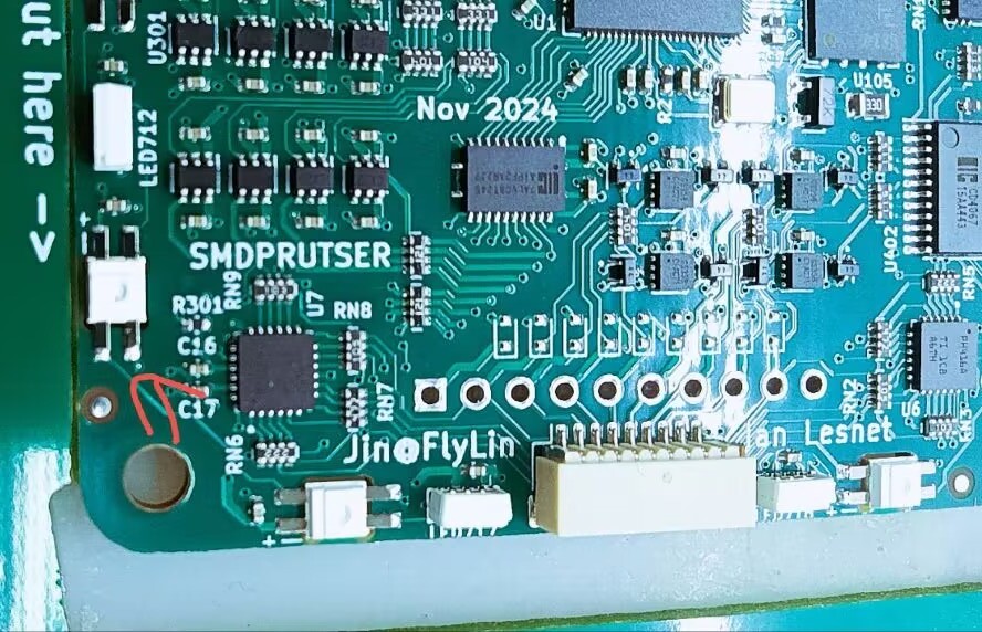
By luck I had 0603 10M resistors in a parts book. Pity, I was looking forward to soldering 10 1M resistors together into some kind of staff.
It fits right where the unpopulated TVS diodes would go.
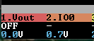
IO0 is now at 0 volts.
It’s cold in there today, and Schottky diodes leak way more when they’re warm. I cooked the board on a space heater to 50c and there is indeed more leakage.
Around 30c the leakage amounts to 0.1V. Around 26c it started to bounce from 0.1 to 0, and at 24c it was solidly 0.
I will add 10M pull-downs to all the pins, put the board in a case, and see if self-heats enough to show leakage.
After 30 minutes in the enclosure with LEDs and LCD running most of the pins start to float at 0.1V.
I’m looking into more heavy handed solutions:
- Additional I2C expander with 1M pull-down not powered by VOUT
- Some kind of FET array we can control with one pin from the auxiliary XL9555 IO expander.
- Some kind of buffer with output enable/HiZ control and all the IOs connected to ground