That situation doesn’t sound good. Right now, Core0 sends messages to Core1 and sometimes waits for response. Moreover, it’s an unwritten rule that Core1never blocks waiting for a resource. If it does, it will have effects on USB, display, and more.
Caution and care are recommended. And obviously, it’d be better to stay as single-core as possible (if possible).
Could you help me better understand why a power change on VREF would force doing stuff in lockstep with Core1?
For example, is there some dangerous condition that requires real-time responsiveness, and thus must occur from Core1? If so, wouldn’t the mutex negate the real-time responsiveness?
The way it is structured now core 1 does a sweep of analog voltages every 500ms. This handles the current limit fuse blow detection. That would be the obvious place to add tracking of VOUT if low then high, send the pullx configuration again on each loop, until write verify returns true.
The other option would be to push a command through the inter core FIFO and process the pullx reconfiguration as part of the core 0 service loop.
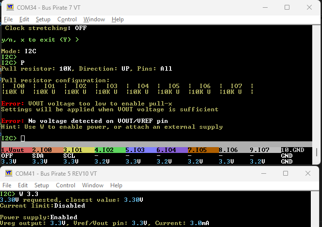
When VOUT drops below 1.2ish volts (1.65v according to data sheet, but I’ve found real life is messier) the IO expander chips that handle the pullx resistors are reset.
I’ve handled this when the Bus Pirate PSU changes, but we also need to consider if the user connects an external voltage.
Suddenly we go from 0volts (pullx chips unpowered) to 3.3volts (or whatever), with no user action on the Bus Pirate. The Bus Pirate then needs to reconfigure the pullx because the chips are now active. That is the point of the detection.
I also now realize I’ve basically created a little race condition if user does W 3.3, second core will pick that up too, so thats great as well.
The XL9555 that is planned for BP7 Rev1 has 16 IO pins, but currently not all of them are used. You could use 8 pins from it to directly do the 1M pulldowns, without needing any additional IC.
The MC74LCX244MN2TWG you suggested in the other thread would be another option, but it would be one more IC.
Unless all the IOs from the XL9555 are actually needed I’d not add another IC.
The Abs. max voltage for the IO pins of the XL9555 is 6V, independent of Vcc. So powering the XL9555 with 3.3V would still allow to use the IOs with 5V.
This is under consideration, certainly, and would be the most frictionless solution. It is 8 traces under a crowded section of the board so it makes me a bit nervous. I sent some info to Supul (routing board) and look forward to a discussion soon.
It is such a simple thing, 8 open drain outputs with a single control, but the miniature options to do it are a bit sparse.
Ah, yes. The user could first configure the pulls, then plug in some voltage to VOUT, disconnect VOUT and the reconnect VOUT again. For example because the wire to VOUT isn’t properly plugged in or the user wiggles the cable. Then the pulls should automatically work again as configured once VOUT is powered again. This requires some service loop dealing with this in the background.
Talking to the I2C expanders that do the pulls is something that is expected to be error-prone: when they are not properly powered, they won’t answer. So I don’t think it is a good idea to do this in a service loop that needs to stay responsive.
So to me the FIFO message to core 0 sounds like the better solution. But I’m not really familiar with this part of the firmware, so I might have missed some detail or other solution here.
Added a mutex for sharing I2C across cores, much like SPI. Wrapped all I2C access in the mutex.
        if (lcd_update_request) {
            monitor(system_config.psu);
This is triggered every 500ms on core1, it updates the LCD and status bar. The monitor does a fresh ADC sweep of all the analog inputs, so hw_adc_voltage[HW_ADC_MUX_VREF_VOUT] can be reused for brown out detection.
Boards have started to arrive to testers. First test is not great…
The UF2 bootloader does not connect.
Long/short button press does not activate bootloader
Chip can be programmed via SWD
Firmware programmed by SWD works
Jumping to bootloader with $ does not activate the bootloader
Assembly seems to be ok. The chip does work, but the bootloader/boot ROM seems to be damaged or corrupted.
Looking at the otpdump everything seems in order.
So far we’re at 50% QC fail rate on the RP2350Bs from the market. Curious to see how the other two boards shake out.
The chip markings indicate these chips were made the 27th week of 2024, which is newer than the chips that went into production Bus Pirate 6 (19 week of 2024).
The batch marking is a bit odd, but that’s almost certainly a coincidence. I’m not going to post it. If this is an under the table operation I don’t want to mess up some poor uncle’s day from half way around the world.
Some possibilities:
Totally random one-off
ESD damage to the chips in cut tape at supplier, during transport or during assembly
I believe the UF2 bootloader runs from the internal RC oscillator(?), it could be out of spec or poorly calibrated
These are QC fail dumpster dive chips
@Dreg this may impact new production of Bus Pirate 6. If the issue crops up in a second board then we can’t trust this supplier.
strange what kind of issues creep up when developing new hardware…
So when you can run code via SWD, you should be able to read out the code of the bootloader and then compare it to a working one.
Also you should be able to run code from the internal oscillator and activate the clock-output and then measure the frequency from the outside to verify the frequency, potential jitter and so on.
Or it is some issue with the new bootloader activation circuitry or the PSRAM? Maybe something with the pullups/pulldowns that sometimes makes the MCU try to boot from PSRAM and fail or something like that.
One of my RP2040 boards had an issue when the power supply voltage was rising too slow: the RP2040 undervoltage reset is on the 1.1V domain, so it releases reset when the 1.1V are stable. But the NOR flash isn’t ready at those voltages yet. So I had to add an external voltage monitoring IC that keeps reset below 2.9V to make it boot reliably in these cases. Could be something similar here too.
The board I received worked right away, so I think it is specific to this chip. We manufactured 500 Bus Pirate 6 with the same basic setup and didn’t encounter this issue once, but it could be a rare corner case.
It is unlikely to be the bootloader activation because $ should still work in that case.
It will be interesting to see if you and @henrygab have any similar issues.
Those people that got a defective Rev7 could try to plug it into another PC or connect it via a powered USB hub and see if it works there. This would be an easy test to vary power supply voltage rise time. Also maybe try a different USB-C cable that has lower resistance on the power lines.
My Rev7 is still in the post, but today it showed up in Germany at the first post distribution center. So it will probably arrive tomorrow or Monday.
then you could animate a hand that moves a soldering iron.
Other ideas for the root cause: it could be related to OTP. Like misconfigured or misread data from OTP that tells the bootloader to not activate or just activate the serial mode.
So reading out the OTP area from a defective unit would also be interesting.
Updated self test to cover each pullx resistor value.
TEST RP2350 E9 BUG FIX
ERROR: BIO0 shows E9 behavior
Much to my embarrassment the 7R0 schematic was not updated with the fix for E9 @electronic_eel is a little too on the nose with that sticker suggestion. It doesn’t pose any problems testing the new features, but it still stings
All other values appear reasonable and appropriate:
Row 0xF80: PAGE0_LOCK0  -- No key required for R/W
Row 0xF81: PAGE0_LOCK1  -- Page is R/O for all uses
Row 0xF83: PAGE1_LOCK1  -- Page is R/W by Bootloader and Secure software
Row 0xF85: PAGE2_LOCK1  -- Page is R/W by Bootloader and Secure software
Row 0xFFD: PAGE62_LOCK1 -- Page is R/W by Bootloader and Secure software
Row 0xFFF: PAGE63_LOCK1 -- Page is R/W by Secure software only
My unit arrived, and it loaded up the bootloader without issue.
Firmware loaded fine via the boootloader, and screen showed BP7 and all voltages at 2.0V .. 2.2V … which is expected.
However, the firmware isn’t playing nicely with my Windows box. It complains about Device Descriptor Request Failed. Removed all traces of the device and re-inserted … and now it’s not appearing at all.
I tried to push the reset button the bottom … only to realize it’s not there. Double-pressing the physical top button, long-pressing the physical top button … neither one causes any reboot of the device.
Have not attempted access via SWD (yet).
RECOMMEND TO CHECK:
Is the physical USB-C connector’s connection solid?