Glad it bootloaded. Weird USB issue. If the bootloader works then the physical USB connector should be OK.
The bottom button is there, but the location changed you’ll have to take the case off until we have a batch with the hole relocated.
I knew we would have to change the button hole so we made it an insert in the new tooling. When the new location if final, the tooling with be modified with a new insert to cut out the new button location.
You did this on purpose: we all know you really enjoy making stickers, so you wanted to make sure that there is a reason to make a “I fixed my 7” sticker.
This is a dump from one of the not-bootloading defective units?
Another thing to try on a defective unit would be to heat and cool the whole pcb. Just a bit with a hair dryer and putting it in the freezer for like half an hour and directly try the bootloader after getting it out again.
The issue could be caused by some diode leakage, FET threshold voltage or similar thing, and because we are right on the margin of it appearing or not, just some units are affected. Heating and cooling should shift those things up or down. If the issue is gone with heat or cold, then we got a good indication that it could be some design issue and not a bad batch of RP2350.
Ok, so we currently only know about one affected unit. Could also be some strange solder defect or something.
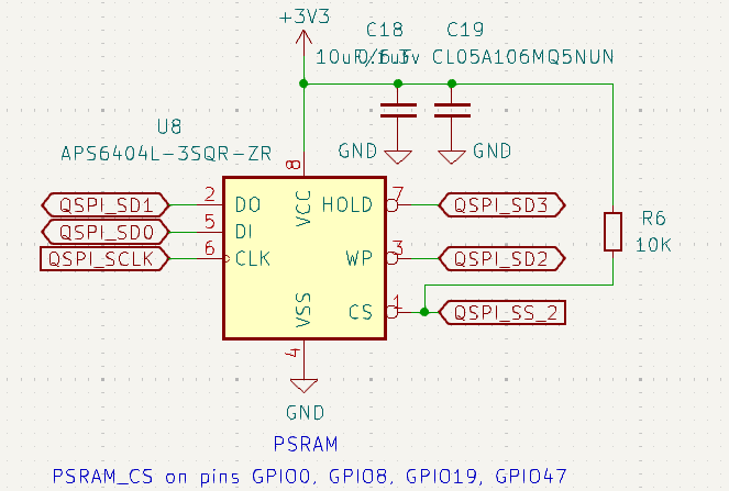
I just browsed through the RP2350 datasheet and it looks to me like the described behavior would be consistent with QSPI_SD1 being pulled high. This would select the UART bootloader instead of the USB one and if I understood it correctly, this would also happen when you trigger BOOTSEL via command and watchdog.
What is new with Rev7 is the PSRAM. And that is also connected to QSPI_SD1. So it could have some leakage there or similar that sometimes causes QSPI_SD1 as being detected high during this bootloader check sequence.
@phdussud could you try to connect a pulldown to ground, like for example 4k7, to QSPI_SD1? I guess the easiest position to do this would be pin 2 of the W25Q128JVSIQ NOR flash. If this is indeed this issue, it should be fixed by this and the bootloader now work via USB instead of UART.
Of course this must not be leakage, but there could be a short on the PCB that causes this. For example between pin 1 and 2 of the PSRAM. We have a pullup on pin 1 there and that would cause this effect while the NOR flash would continue to work normally.
Ok this is the issue. I measure 2.2V on this pin. If I short it with my uA meter, I see it sourcing 300uA. If I then long press the bootsel button, the USB bootloader comes up.
So now the question is where is this voltage coming from.
It could be a short with some other pin. Could you try a continuity check against pin 1 of the PSRAM? Maybe also against the pins that are next to QSPI_SD1 on the NOR flash and on the RP2350.
Another reason could be that the PSRAM somehow doesn’t hold this pin in HiZ, but tries to output some data on it, it is data out. But then I’d expect a higher voltage and less impedance.
What voltage do you measure on pin 1 (=chip select) of the PSRAM? I would expect 3.3V there, so that the PSRAM is disabled. If you measure something lower there, does pulling it up to 3.3V also fix the issue?
What about pin 1 of the NOR flash? Same thing as the PSRAM, it could somehow decide to output data on QSPI_SD1 because it’s chip select gets activated when it shouldn’t.
For now I’m more leaning towards the solder defect as the root cause.
I am now able to get this to enumerate on the USB port. Other times, the device descriptor sometimes is reported as zero-bytes in length, and then Windows refuses to talk to it without drastic measures (USB cleanup using tools from www.uwe-sieber.de). NOTE: This issue may be due to use of USBIPD. If not, the issue exists in BP5 / BP6 also, as I recall seeing this occasionally before.
@Ian I can reboot using $, and it drops right into the bootloader (and showed as UF2 drive again) … no issues whatsoever.
However, the internal NAND … Attempts to format my internal NAND fail, and no files appear to exist. I’ve not done any investigation on this yet, just noticed that my LED config was not being saved, and tried both ls and format…
About the PCB.
No short between the adjacent pins to pin 2 of the PSRAM. All pins voltage of the PSRAM chip seem OK. CS (1) is at 3.3V and WP (3) is at 3.3V
When there are no shorts and the chip selects are high, just leakage from the PSRAM, NOR-flash or the RP2350 is left as source. At 300µA this can’t be just wider tolerances or such, this must be a defect in one of the chips. It could for example be damage from ESD.
You could try to pull it down with a 2k7 like you suggested. But I’m not sure how long it will last because it is not unlikely that the damaged IC will further degrade with time and use.
@henrygab has these not fully diagnosed yet issues with the NAND and USB. This is also something that could be caused by ESD.
I guess this was just a very small production run, with just the 4 or maybe 10 units made, correct? It could be that the assembly house didn’t work properly because it was just a very small batch.
I’ve had this issue myself with a project at work. I ordered (and payed for) full service PCBA with everything, but the small test batch had an enormous failure rate for some LEDs, like 5% of them were damaged and didn’t light up green, while R and B were working. When I ordered the bigger batch later everything was ok and none of the LEDs was damaged. I suspect either a very bad solder temperature profile or ESD as reasons, but I didn’t do a thorough investigation. It could be something similar here.
Another thing could be that the new supplier of the RP2350 wasn’t careful enough and they were ESD-damaged during handling, re-reeling or similar.
NOR is Winbond, the chips we’ve used for years without issues. PSRAM is new, it’s the same brand lots of dev boards use and I have no experience with it.
It could certainly be a handling issue anywhere in the chain, but we’ve never had a problem with the proto PCBA. They are super professional.
I am probably too quick to blame the RPi distributor, but there were a lot of warning signs that something isn’t quite right…
The representative couldn’t actually sell them, instead someone else dropped by later giving only a surname (I’m not making this up)
Leaving out some other small details, this feels like a good way to get poorly handled or grey market stuff. Usually cell phone parts, but it has that feel.
The good news is our normal scalper can now get them from reliable suppliers and we should have stock Monday. 7REV1 will be done in the next few days, and we can self-test before shipping this time.
Oh, that really sounds dodgy as hell. No wonder you suspect the RP2350 as source of the issues.
That sounds good. But even if there are multiple issues with the 7Rev0, I suggest to still learn what we can from it before starting production of 7Rev1.
While for example you have made the new pulls configurable, there isn’t yet firmware for advanced usage of them, for example for impedance measurement. When implementing this we could find out that a different selection of pull resistors (or something else) would be a better choice. And then use 7Rev1 to see if that change is indeed an improvement.
Or at least some very basic usage of the PSRAM to check accessing it and see if there are any issues with it that we don’t know about yet.