I did a fresh build on my BP6. Here’s the command when I execute
python i2c_example.py -p /dev/ttyACM1 --device 0x80 --register 0x00
And here’s the trace. I modified i2c_example.pyto use 100000 instead of 400000 bu other than the one line, the debug output was identical.
HiZ> [BPIO] COBS delimiter found, stopping read[BPIO] Flatbuffer data read complete, total length: 102[BPIO] Packet Type: 2[I2C] Speed 400000 Hz[Config Request] Mode changed to ‘I2C’[Config Request] PSU current limit override enabled[Config Request] PSU Voltage: 3.300000, Current: 0.000000, Override: true[Config Request] Power supply enabled[Config Request] Pull-up resistors enabled[Send Packet] Length 36[Send Packet] COBS encoded buffer length: 38[BPIO] COBS delimiter found, stopping read[BPIO] Flatbuffer data read complete, total length: 50[BPIO] Packet Type: 1[Status Request] Query types: 0[Status Request] Version requested[Status Request] Modes available requested[Status Request] LED count requested[Status Request] Pullup status requested[Status Request] PSU status requested[Status Request] ADC status requested[Status Request] IO status requested[Status Request] Disk status requested[Send Packet] Length 548[Send Packet] COBS encoded buffer length: 550[BPIO] COBS delimiter found, stopping read[BPIO] Flatbuffer data read complete, total length: 50[BPIO] Packet Type: 1[Status Request] Query types: 0[Status Request] Version requested[Status Request] Modes available requested[Status Request] LED count requested[Status Request] Pullup status requested[Status Request] PSU status requested[Status Request] ADC status requested[Status Request] IO status requested[Status Request] Disk status requested[Send Packet] Length 548[Send Packet] COBS encoded buffer length: 550[BPIO] COBS delimiter found, stopping read[BPIO] Flatbuffer data read complete, total length: 50[BPIO] Packet Type: 1[Status Request] Query types: 0[Status Request] Version requested[Status Request] Modes available requested[Status Request] LED count requested[Status Request] Pullup status requested[Status Request] PSU status requested[Status Request] ADC status requested[Status Request] IO status requested[Status Request] Disk status requested[Send Packet] Length 548[Send Packet] COBS encoded buffer length: 550[BPIO] COBS delimiter found, stopping read[BPIO] Flatbuffer data read complete, total length: 50[BPIO] Packet Type: 1[Status Request] Query types: 0[Status Request] Version requested[Status Request] Modes available requested[Status Request] LED count requested[Status Request] Pullup status requested[Status Request] PSU status requested[Status Request] ADC status requested[Status Request] IO status requested[Status Request] Disk status requested[Send Packet] Length 548[Send Packet] COBS encoded buffer length: 550[BPIO] COBS delimiter found, stopping read[BPIO] Flatbuffer data read complete, total length: 50[BPIO] Packet Type: 1[Status Request] Query types: 0[Status Request] Version requested[Status Request] Modes available requested[Status Request] LED count requested[Status Request] Pullup status requested[Status Request] PSU status requested[Status Request] ADC status requested[Status Request] IO status requested[Status Request] Disk status requested[Send Packet] Length 548[Send Packet] COBS encoded buffer length: 550[BPIO] COBS delimiter found, stopping read[BPIO] Flatbuffer data read complete, total length: 66[BPIO] Packet Type: 3[Data Request] Start main condition: true[Data Request] Start alternate condition: false[Data Request] Bytes to write: 2[Data Request] Bytes to read: 8[Data Request] Stop main condition: true[Data Request] Stop alternate condition: false[I2C] Performing transaction[I2C] START[I2C] Writing 2 bytes[I2C] Write address 0x00[Data Request] Protocol request failed[Data Request] Error: Protocol request failed[Send Packet] Length 88[Send Packet] COBS encoded buffer length: 90
ian
December 7, 2025, 3:28pm
22
Thank you so much!
[Data Request] Bytes to write: 2[Data Request] Bytes to read: 8
data = i2c.transfer(write_data=[device_addr, register_addr], read_bytes=read_bytes)
Ahhhh… Given the multiple calls to status query your using the i2c_basic_example? This looks correct.
Write address 0x00 is incorrect, but it appears to be a debug display issue:
if(request->debug) printf("[I2C] Write address 0x%02X\r\n", flatbuffers_uint8_vec_at(data_write, 0)&~0b1);
This line needed to be updated to use the flatbuffers vector, but that’s not causing the error. I’ve pushed a fix, but this is cosmetic only.
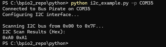
PS C:\bpio2_repo\python> python i2c_example.py -p COM35 --device 0xa0 --register 0x00
Connected to Bus Pirate on COM35
Configuring I2C interface...

Current mode: I2C
PSU enabled: True
PSU voltage: 3330mV
PSU current: 3mA
Pull-up enabled: True

Reading 8 bytes from device 0xA0, register 0x00...
Read data: 48656c6c6f20576f
Read data (hex): 48 65 6C 6C 6F 20 57 6F
Here is what I get when I run the example with a 24C02 EEPROM.
Have you also tried on a Bus Pirate 5? I’ve done most of my testing with 5.
I just tried it on my BP5. The only difference in the debug output is the output error you just corrected.
1 Like
ian
December 7, 2025, 6:03pm
24
I’m sorry, I’ll have to think it over a bit more. Everything seems OK.
Are you able to write to spi (with or without device attached)?
Let me try that.
That works (once I found a good flash chip)
python spi_example.py -p /dev/ttyACM1
1 Like
ian
December 8, 2025, 3:55pm
26
That’s encouraging.
So we have 2 Bus Pirate (5, 6) that both do I2C ok in the terminal, but fail with the python script? SPI works ok. The failure seems to be sending no data or clock at all, and failing at the address write.
Is that a somewhat correct summary?
Yes. Also i2C scan fails.
1 Like
ian
December 9, 2025, 11:35am
28
I’m sorry, I’m really stumped, and can’t get anything similar to happen with any of the hardware I have here.
It works in the terminal, so the hardware should be ok and the chips connected correctly.
Problem on 5 and 6 hardware
SPI works.
We see the data is getting to the bus pirate flatbuffers interface in the terminal debug
It appears start and stop are being issued, but no data
Is there something like a Logic Analyzer with Bus Hold pins hanging on the bus? Unlikely, but…
What happens at 20kHz or 50kHz?
Here is what I would do next to debug:
Increase the I2C pull-ups to 2K or so with external pull-ups
Slow speed to 50kHz
Run the scan and capture the full scan in Logic 2.
Save the capture, compress, and upload here.
Then I can have a look at what is happening on the full 256 address scan.
1 Like
I’m getting inconsistent results. I have to research this some more. I’m beginning to suspect one of my I2C sensors is causing issues.
2 Likes
ian
December 9, 2025, 7:06pm
30
In this one I notice your SCK line is idle low. Maybe something is hanging onto the bus? Clock stretching? It doesn’t look like the start condition is decoded by the logic.
1 Like
Changing frequency and clock stretching does change the results, so I wanted to get a baseline condition.
Is it possible that the si7021 command leaves an HTU21 sensor in a state that might make a scan fail? i.e. It changes the configuration to be in Hold mode?
Perhaps I had clock stretching off when I was doing a scan, and the sensor was in hold mode which requires clock stretching. Does that make sense?
I’m also looking for an example of a python invocation of a i2C device, that I can compare that I get the same results. But I’m not sure how to replicate some of the advanced terminal commands using python,i,e, this example form the si7021 tutorial
[0x80 0xe7[0x81 r]
I’m also looking for a simple I2C sensorso we can duplicate results.
2 Likes
ian
December 10, 2025, 5:07pm
32
[0x80 0xe7[0x81 r]
Off the top of my head, use the i2c transaction function like so:
I2c.transaction(write=[0x80 0xe7] , read=1)
It will handle the 81 read address automatically.
1 Like
I’m still having problems getting the python+I2C commands to work. I’m having a problem even if I directly connect a breakout board to the BP.
I am looking at the debug output. In particular, the debug output says
[Data Request] Stop alternate condition: false[I2C] Performing transaction[I2C] START[I2C] Writing 1 bytes[I2C] Write address 0x00
Why is the write address always zero? When I do a scan, shouldn’t it change? I would expect the scan to iterate through the device address and have this reflected in the debug code. But I never see the different addresses. Also - when I explicitly specify the device address and register using the i2c_example.py arguments, shouldn’t it change? For example, I’m using “–device 0x32 --register 0x20” and the write address is still 0x00.
Packet Length changes, but it never prints addresses or registers in the debug output. This doesn;t seem correct.
If I could find a I2C sensor that we have in common, and the working python code that does a simple query to this sensor, it might help. I have several (i.e. LIS3MDL, RT3000C, LM75B, si7021, TSL2561,HTU21D, and some from the common Arduino sensor kits).
1 Like
ian
December 20, 2025, 10:57am
34
I thought that was a debug output display bug that I fixed a while back. Is it still happening?
My mistake. I switched from BP5 to BP6 and forgot to update the firmware.
I’m still struggling getting i2c scan to work. in python, even with a simple breakout board.
1 Like
Sorry again. Here’s the right debug output. I did a scan using python. Then I switched to the CLI and immediately typed “scan” and the CLI version worked. So the BP/I2C configuration in the CLI is the same as the python configuration. Yet the python code fails with a
[Data Request] Protocol request failed[Data Request] Error: Protocol request failed[Send Packet] Length 80[Send Packet] COBS encode
Here is the full debug output showing the (a) debug output, (b) results of the CLI scan, and (c) the BP version
out3.txt (2.1 KB)
1 Like
To be clear, I have three I2C devices connected and the CLI reports
I2C> scan
Yet with python code fails to find them. Exact same setup and parameters.
1 Like
ian
December 22, 2025, 12:46pm
38
[I2C] START
[I2C] Writing 1 bytes
[I2C] Write address 0xA0
[I2C] STOP
[Send Packet] Length 48
[Send Packet] COBS encoded buffer length: 50
[BPIO] COBS delimiter found, stopping read
[BPIO] Flatbuffer data read complete, total length: 66
[BPIO] Packet Type: 3
[Data Request] Start main condition: true
[Data Request] Start alternate condition: false
[Data Request] Bytes to write: 1
[Data Request] Bytes to read: 1
[Data Request] Stop main condition: true
[Data Request] Stop alternate condition: false
[I2C] Performing transaction
[I2C] START
[I2C] Read address 0xA1
[I2C] Reading 1 bytes
[I2C] STOP
[Data Request] Returning read 1 bytes
I’m sorry, I’m unable to reproduce this. You have stock firmware and unmodified python library, I don’t know what could be the difference between your setup and mine.
The full Saleae Logic capture of the scan command via python and via terminal would be the next step in debugging.
What device are you scanning?
1 Like
ian
December 22, 2025, 7:31pm
40
24c02 eeprom for this test, but a lot of other things (adafruit moisture sensor, RFID chip, etc) for previous tests.