DDR4 and DDR5 parameter table reader

I2C> ddr5 write -f udimm.bin
Write SPD NVM from file: udimm.bin
Device Type: 0x5118
Write Protect Override is enabled, proceeding with write
NVM block lock bits cleared, proceeding with write

It’s REALLY messy, but write now works. I wrote the dump of the udimm module into the sodimm module.

SPD EEPROM JEDEC Manufacturing Information blocks 8-9:
Module Manuf. Code: 0x859B (Crucial Technology)
Module Manuf. Location: 0x00
Module Manuf. Date: 22Y/04W
Module Serial Number: 0xE6FFB785
Module Part Number: CT8G48C40U5.M4A1
Module Revision Code: 0x57
DRAM Manuf. Code: 0x802C (Micron Technology)
DRAM Stepping: 0x41

Running the probe command on the SODIMM (SK Hynix laptop memory) now shows that it is a Crucial UDIMM :wink:

Next I’ll do a massive cleanup on this code, which will probably result in at least two new system wide abstraction layers for working with I2C and files.

1 Like

This turned into a beast of a command, but I think it was worth it as a template for future similar commands.

The DDR5 command is in the main firmware now, I believe it is complete (for now). Next I’ll do the docs while it’s fresh in mind so we don’t fall behind again.

3 Likes

amazing this produck

1 Like

Draft documentation is live. It’s very much a framework that still needs fleshing out, there’s no snips or casts and a lot of the text is still in outline form.

I think I can finish this up in one more day.

Argh! Couldn’t do it, but got it mostly done:

TODO:

  • Write the two opening paragraphs for DDR5 demo. Don’t have enough juice in the tank for that kind of editing right now.
  • Plank adapter page (need to finalize the hardware first)
1 Like

REV1 board routed:

  • Swapped PWR and PGOOD LEDs, I think that makes more sense logically.
  • Changed 2K pull-ups to 10K
  • Changed 2N7001 FET to BSS138 (future update: use dual package BSS138PS)
  • Rounded the corners
  • Will be made on 2mm thick PCBs for strength

We of course need to test this revision, but I think this is production ready.

1 Like

This board arrived and it looks great! The 2mm PCB is much stiffer.

However, the bidirectional level shifting remains buggy, even worse than before.

Bringing out the big guns and using a TXS0102 bi-di level shifter.

Got it routed, will send out the next rev now.

2 Likes

Still trying to understand why this is not working. I have an adafruit breakout board that uses the same circuit, and it works fine.

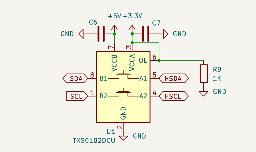
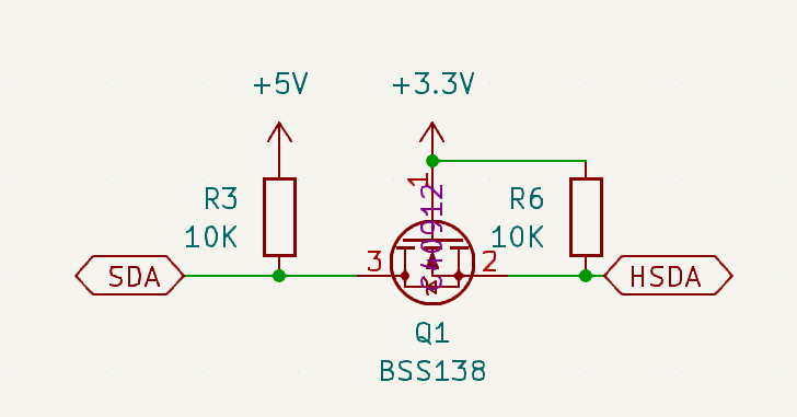
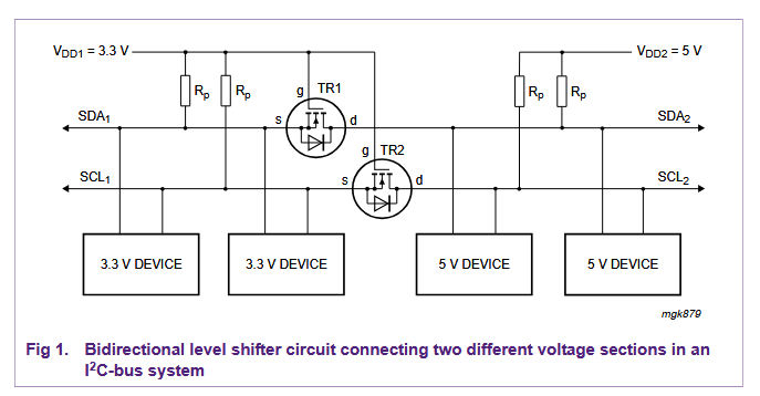
From the app note describing this technique, as well as sparkfun and adafruit schematic, everything looks fine. Drain pin is to the higher voltage side, source is to the lower voltage side. Gate at low voltage. (Note that our ddr5 schematic is 5v left, 3.3v right, while the app note is opposite).

Test 1

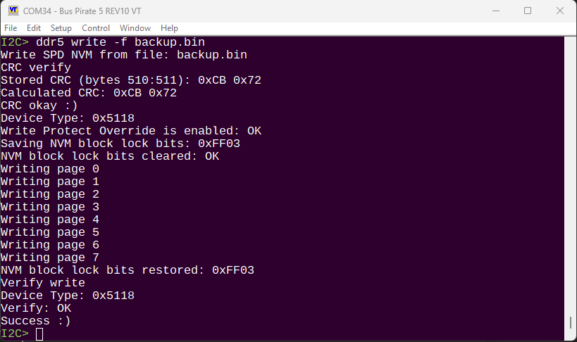
Rev 0 used 2n7002 fets and 2K pull-up resistors. The pin wasn’t pulled far enough to ground when 0, so I2C didn’t work. I fixed this by replacing the 3.3v side 2K resistors with 10K, removing the 5v 2K resistors and using the onboard 10K pull-up instead. DDR5 SPD chip worked fine at 400khz after mods.

Test 2

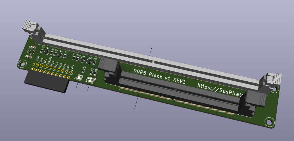
Rev 1 used Diodes INC brand BSS138 (same part number as SF, adafruit, etc) with 10K resistors on high and low sides.

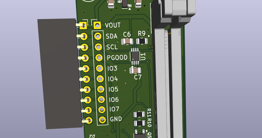
Board 1: Just powered with no DIMM and I2C unconnected. SDA sit at 3.9V, SCL 4.3V. Pulled low, SDA is 0.4V and SCL is 0.9V. Some of this is due to voltage divider formed by the Bus Pirate series protection resistors, but that doesn’t account for such high (and different) values.

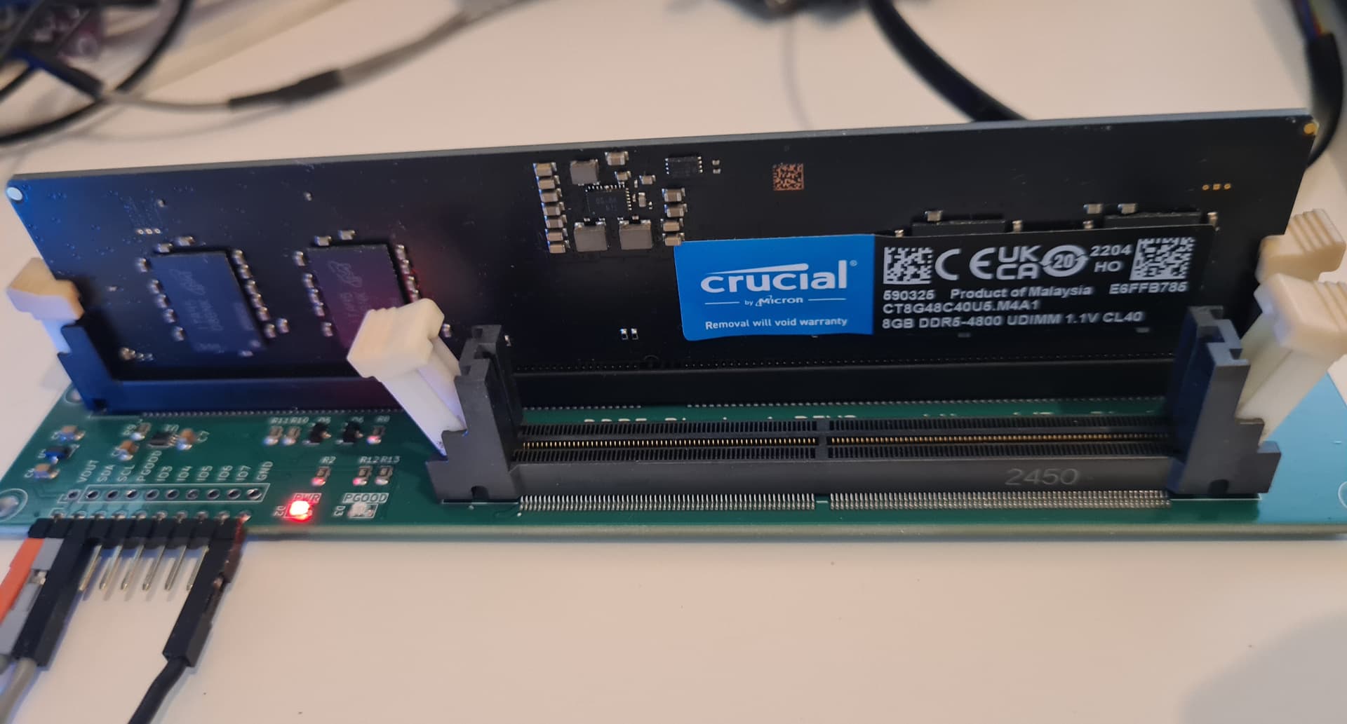
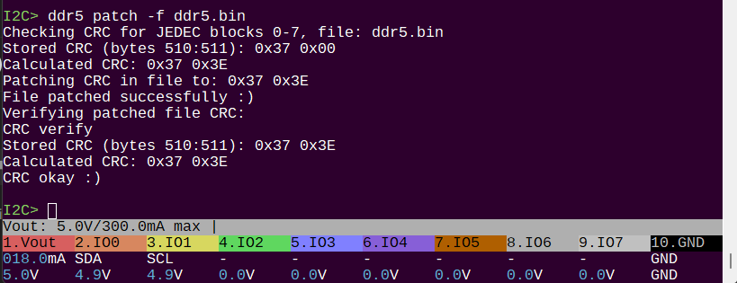
Board 2: Powered with no connection: SDA 4.9V, SCL 4.6V. Pulled to ground both read 0.3V. 4.9/0.3V is similar to the adafruit soil moisture sensor which has the same circuit. I can work with the DDR5 udimm if the I2C speed is <100kHz, so much slower than rev0.

Something is wrong with board 1. Something seems to be wrong with board 2 SCL. Parts look correct and soldered well. Resistors are all the right value and 1%.


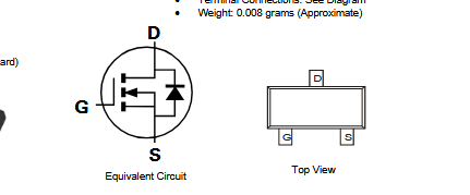
I triple verified the pinout of the parts we used on paper printouts.

Next steps

Is it possible there is so much variation between individual FETs? Have I missed something completely obvious?

I guess the next step is to rework all the parts and made sure no connections are bad.

I switched to a dedicated level shifting chip to remove any chance for this weirdness. However, the Qwiic/Stemma QT adapter is intended to work with boards with the same setup, so if we’re having problems here it will be an issue there as well. The Stemma I2C board I have works fine, and I have a few more StemmaQT boards on the way to test further on Tuesday.

Mystery remains unsolved.

1 Like

Latest version of the DDR5 board arrived. This one uses TXS0102DCU bi-directional level shifter to translate between 5 and 3.3 volts. It’s reliable, but the max speed I can get is around 300kHz. Not sure if this is poor board design, the cable length, or some other issue. The TXS0102DCU should work at up to 2MHz.

Going to have to look at it under a scope.

the moment when you need to get out the big guns…

1 Like

Checked the Bus Pirate side, which isn’t exactly helpful, and it looks okay. I didn’t leave myself any test points on the PCB, so checking the 3.3volt domain is going to require some board surgery.

This one should be done soon. I believe it is at (or on the way) to assembly.

Been hunting for some kind of board to edit SPD data on UDIMM DDR5 sticks I have here. What is the projected timeline and cost to order one of these?

1 Like

Hopefully next week. I don’t know the final cost yet, maybe 20ish bucks, but I really need the final accounting when everything is done.

Perfect, exactly what I need. Will you post them up on the site like the rest of the components? Looking forward to this, you have done great work on these!

1 Like

Yes, everything will go up on the docs,distributors list, and in the dirty PCBs store. I’ll also post something on social media if you follow us anywhere.

Here’s the docs for the ddr5 command for working with the SPD, let me know if anything is missing:

I see the command to check and correct the checksum, are you able to edit the bin file directly, or does that require outside software for editing? My initial desired use of this project, is to slightly edit the SPD in my sticks by one value to change the model family.

1 Like

Editing the dump file is usually easiest with a free text editor like HxD or similar. I can add an option to ddr5 to update the CRC so it is correct after your changes.

Added patch action to ddr5 command. Docs updated and new firmware pushed.

2 Likes

This board is now available at DirtyPCBs.

1 Like