So this plank is also for DDR4? Pins are the same. If so its my next buy of plank collection. And will try to overclock servers’ DDR
1 Like
This plank is only DDR5 SODIMM (laptop) and UDIMM (desktop). It does not support DDR5 RDIMM (server ram with EEC).
My server uses SODIMMs😎 but DDR4. Will it work?
1 Like
Unfortunately not. I think the socket is different, and it defo needs 9volts to get into programming mode.
If DDR4 is still in wide use, I’ll look into it. I thought it might be a bit old.
Old? I am still rocking on DDR3 on my daily driver laptop😅
2 Likes
Good to know!
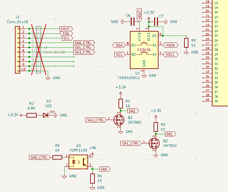
DDR4 adapter protection circuit and VPP handling.
So far:
- Found acceptable UDIMM and SODIMM sockets. UDIMM has a kicad footprint already
- Read a DDR4 SPD EEPROM datasheet (still a bit confused by some commands)
- Threw together an initial schematic, all RAM pins are protected from >3.3volts. This could be moved to 2.5volts to be in spec.
This circuit will need some kind of external 9V power supply, I’m looking for like a PCB mountable 9volt battery clip.
1 Like
That was super quick. I would like to learn how to do schematix like that. Particulary how to make pin label without drawing a line so each pins are labbeled where they go but components are separate no ugly lines drawn
1 Like
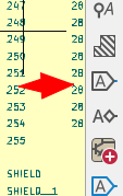
You want this guy to place global labels. There is also an option for sheet labels that don’t connect outside the current sheet, but I find that dangerous.
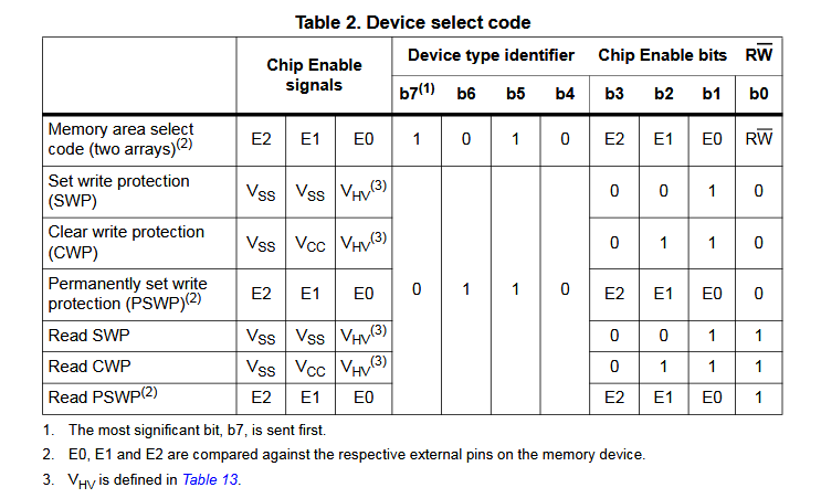
This table from a DDR1/2/3 EEPROM clarified how the “other” commands work.
1 Like
Thanks a lot. I am n00b when it comes to KiCad spent like 2-3h there. That should help with my schematics. Is further routing the board respecting those labels?
1 Like
Yes, the labeled nets will all be connected in the PCB routing area.
REV0 of the DDR4 board is out for routing. I need an initial quick rev so I have some kind of adapter to test.
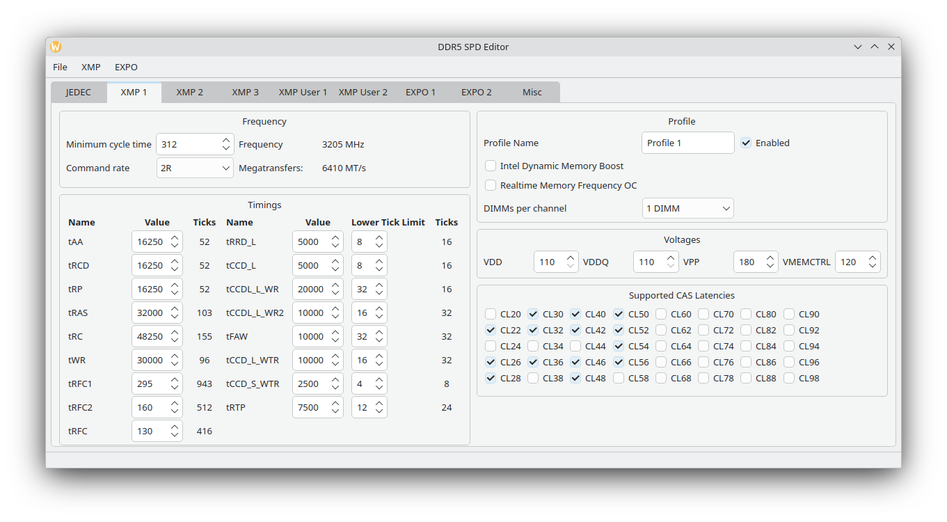
1 Like
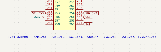
Received the DDR4 SODIMM socket footprint, now the board is ready to route.
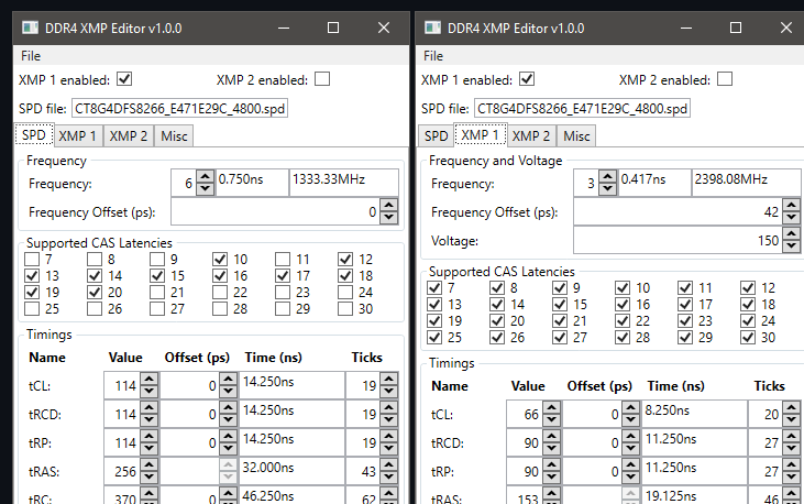
Found a DDR4 SPD editor as well.
1 Like
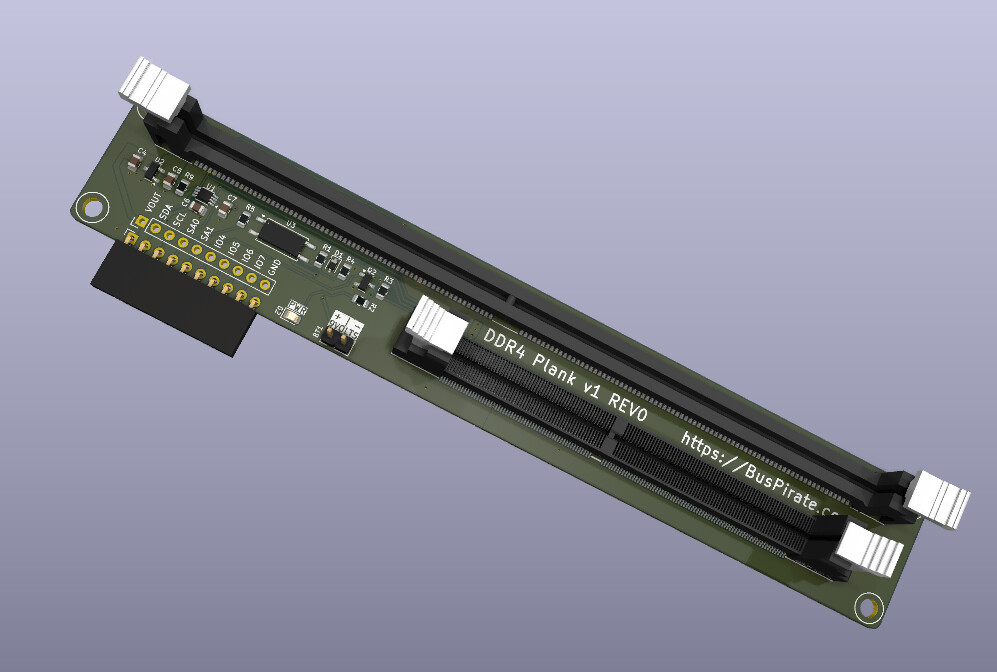
DDR4 adapter 
Will make this ASAP, but China is on a 8 day national holiday so it will be slower than normal.
1 Like
I’m not sure if this goes here, but anyway….
I have a pair of DDR5 16GB UDIMMs. The PMIC on one of them is throwing a PWR_GOOD error. I tried using the DDR5 plank to look at the PMIC registers but the SPD wasn’t responding for some reason. So I took the SPD off and solder bridged the HSCL/LSCL and HSDA/LSDA pads. This worked and I can connect to the PMIC with the plank. It is indicating a SWA under voltage error, but I can’t figure out why. The VDD resistances are similar on both the working and non-working modules. I reset the error flags, but the error comes right back. I don’t think the PMIC is bad because it is working otherwise, but it could be, I guess.
1 Like
As I understand it, the PMIC is not just generating the voltages. It also monitors them and controls power up sequencing. So it might not be that the voltage is off or not working, it could be a chip elsewhere on the module with a problem that causes an error in the power up sequence.
Do you know specifically which error flags are being triggered?
Also very strange that the SPD doesn’t seem to work. Any idea why or what might have damaged the module?
1 Like
The error flags are SWA under voltage and SWB under voltage. I tried monitoring these at power up, but my scope is a piece of junk, so that didn’t work. I don’t know how else to see the voltage at startup. If I inject 1.1V into SWA it draws about 90mA, which is roughly the same as on the good module.
I I’m not sure what happened to the SPD. It was working before . The PMIC had also been working, but I saw that it was producing 2.2V for the 1 1V LDO which powers the SPD VDDIO. So I swapped it with an old one and then this undervolt issue started happening with both. I do have a brand new one but I haven’t tried it because I don’t want to kill it also.
1 Like
The adapter plank is pretty rugged, but does it seem to you like it was a plank issue that killed the SPD? The plank has 3.3volt regulator and an I2C level translation chip, so I’m not sure how it would be over voltage but I will investigate further if you think it was a plank issue.
Did you get a chance to see the SPD chip manufacturer before it died?
1 Like
No, I don’t think the adapter plank killed the SPD. I don’t see how it could. I’ve been using it with the good module and nothing has happened to it. The vendor id in the registers is 0E 8F and the markings on the chip are TD5118ULP 2422. I don’t know which one that is. On the non working module it now has an Ablic S-34HTS08AB.
Normally I would just toss this other module, but with the price of DDR5 these days… Plus it’s driving me crazy that I can’t figure out what is wrong and fix it.
I have a couple of blank DDR5 pcbs coming. If I can’t get this working,I may try transferring the RAM chips to one of those. Reballing 8 chips will be a bit of work, but they’re small 
1 Like
Thank you so much for the update I’m confident the plank is as isolated as possible, but you never can be sure what happens when hardware is loose in the wild.
Weird, the TD5118 doesn’t get any hits. The JEDEC ID, I think, decodes as follows:
0x0e & 0xf = 0x0e = bank [14]
0x8f & 0x7f = 0xf = id = [0x0f -1] (zero index)
From JEP106: [14][0x0f - 1] = "TeraDevices Inc",
TD = TeraDevices? A Shanghai company with no web presence I can find.
Really odd, I think all the modules I’ve used have the Ablic SPD.
Did you program the replacement ABLIC chip non-volatile memory with a dump of the working SPD? You may need to modify the serial number and use the spd command to repatch the CRC (some mainboards don’t like identical SNs).
Yeah, I’m shocked. I did the DDR5 plank a while back and the 4-8GB modules I tested were basically free e-waste. Later I did the DDR4 version and e-waste was basically the price of a new module.
That’s pretty hard core! Please share a photo if you do go down this route.
1 Like
Looking up your vendor ID inspired a new command to get JEP106 IDs in the terminal. It’ll be in the firmware tomorrow some time.
1 Like