Yes, I did. The serial numbers were actually blank on both, even though the packaging had one for each. I programmed them to what was on the package.
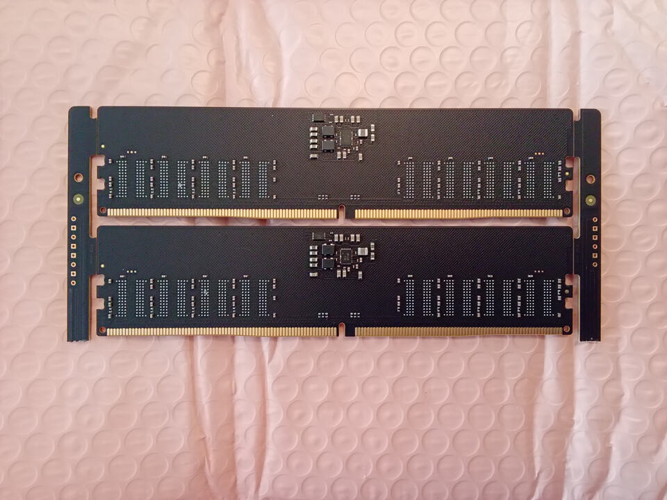
These just got delivered today. They are nearly identical to the ones for the two modules that I have. They have everything on them except for the 82-FBGA RAM chips. The SPD on these is the same TD5118 and the PMIC is a Richtek 5136 (or 5132).
I was playing around some more and figured out how to update the protected registers (0x40 and up) where you can configure a bunch of stuff for each of the regulators. If I use those to turn off SWA and SWB then the PWR_GOOD error goes away and SWC (1.8V VPP) comes up fine.
I also noticed that the status registers are reporting an overcurrent warning for SWA and SWB which would also explain the undervoltage. I figured there must be something on those rails that is drawing current, but I don’t know what. Hopefully it’s not internal to the PMIC.
i think i saw some DDR2 or 3 on the hardware exchange at 39C3. i hope you get better time available there this time. the HW-exchange should be scanned repeatedly there for obvious reasons since stuff spawns multiple times there
I found out what was wrong with the PMIC. It was a crappy soldering job by me! I was looking at it under high magnification and it looked like a few of the pads might not be connected to the chip. I redid them and now the errors are gone!.
For server memory, would I need to supply a clock and change the pinouts to get the side bus i2c from the registering clock driver? It seems like a lot more work.
I’m not sure to be honest. I looked into RDIMMs, but they were so expensive and (I assumed) not commonly used I didn’t buy one.
RDIMMs do require a different socket and UDIMM or SODIMM.
The SPD spec includes overlays for RDIMM, so my wild guess is that it’s a least somewhat similar to UDIMM and SODIMM. The SPD should be accessible via an I2C bus.
I also understand there are additional chips on RDIMM, besides the SPD and PMIC. I don’t know anything about them though.
for DDR3 RDIMMS i could hook you up at the next CCC congress. And like always: CCC community is a good source for stuff like that when needing it for testing (chances are high that someone might have one around with enough RAM errors which don’t matter for your SDP fiddling)
Question regarding the DDR5 plank. I received mine and am very impressed, well done on a great product!
I currently cannot find my BP5 from moving my test lab equipment around, so was trying to use and Arduino UNO with the DDR5 plank. I have the UNO powered by an external 12V supply, USB to PC, 5V and GND out to plank, along with the SDA and SCL directly from UNO to plank. I assuming my issue is related to the pullup resistors. With the BP interface, you activate 10K pullup, I assume I need to add external resistors to the SDA and SCL with the UNO? Tied to what? The Arduino DDR5 program, shows 2K resistors tied to 3.3V for those two lines, but I think the plank handles things a little different, so any insight would be great.
I can communicate with the DDRSPD Read/Write gui program, but I think it is only reading the PMIC and not the SPD file because it is quite small of a file size and doesn’t display the usual data.
You’ll need to power it at 5volts. It has all the internal regulation for everything else.
The i2c level shifter has internal pull ups so you shouldn’t need to add any.
I’m not sure about the arduino program though. What does the dump look like in a hex editor? It should start with spd5118 or something similar (forget the actual string).
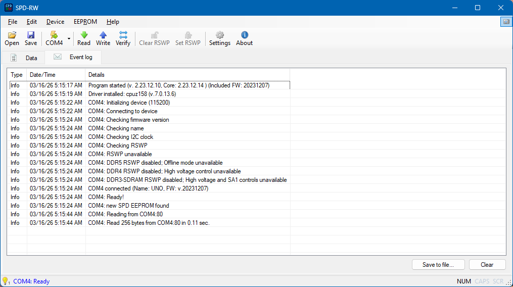
This the read file and what the output log looks like. The 256 size is why I thought this was just the PMIC data and not the SPD. Tried it with two different sticks with the same result. I can read the RAM directly through the SMBUS when it is installed in the PC and get the full SPD file, but I can’t modify the data because the RSWP, so that is why I went with the plank to read/write.
Is the HSA pin always grounded in the plank? Is it routed to any of the header pins?
It is always grounded for offline mode, it is not available at the header. I am uncertain what the app is meaning by RSWP disabled. It could be checking for the SA0/SA1 manipulation hardware in the circuit that goes with the software.
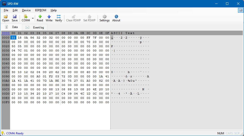
The 256 byte file is really strange. It has the 5118 signature in the first two bytes, so that is from the configuration registers that also have temperature sensor etc. That region is 128 bytes though, not 256.
The area you’re probably most interested in is the 1024 bytes of non volatile memory that contain the actual SPD records. It doesn’t start with 5118. Maybe the application has some config switch to choose between registers and NVM?
Yes, this program I found can communicate to the DRAM either through the SMBUS directly to the PC motherboard when the sticks are installed or outside of the motherboard with the Arduino and the plank. I can read and write through SMBUS and get the full 1024 bytes but you cannot disable RSWP when they are in use. That was what brought me to the plank.
So there must be a conflict in the Arduino firmware or settings file that is not shaking hands with the plank. I will spend a little more time looking at that, but I may end up just buying a BP6 if I can’t find my BP5 which I think is a lost cause.
This is the GitHub project, not much documentation and no real activity in a while. The BP6 approach is far superior and useful it seems.
It’s also odd that the arduino app checks ddr5/4/3 all, so I’d guess it’s a general hardware check. You might fool it by holding the sa0 sa1 pins high or low if it is a hardware test.
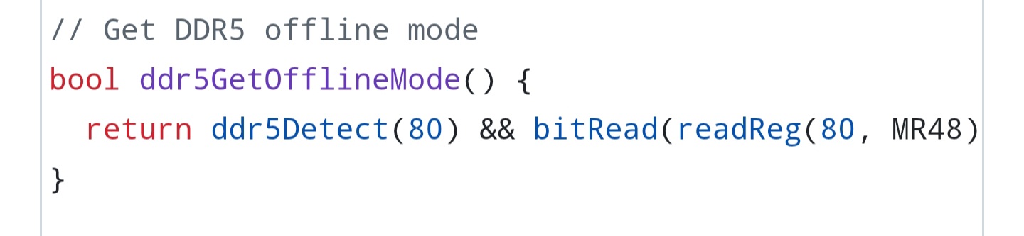
I’m very familiar with the hardware for this project, I studied it while designing the planks. I’m not sure how it would test, but I tried to look at the schematic and firmware again and get repo errors.
This is what it’s doing. I’m on mobile so don’t have full code coverage, but it seems to be reading register 48 and checking a bit. 48 is device status.
Hi there! Thanks for making such and an awesome product!
I have a question regarding the ability to allow manual vdimm control on locked sodimms. Please excuse any of my ignorance as I do not have any experience with memory spd and pmic.
It seems that the is a ‘secure enable’ on ddr5 dimm/sodimm and I am guessing this is the RSWP(though I could be wrong). Can be found to be enabled or disabled through something like hwinfo (not that you can change it there, just what it reads).
My endgame is to unlock manual vdimm control on a pair of Samsung sodimm ddr5 modules. Currently, they are fully locked to 1.1v (to the dram moduals from the pmic) with no xmp/expo profile and with the above ‘secure enable’ set to true
I was wondering if there is a way to either disable the lock or if merely creating a xmp/expo profile could be used as a workaround. The former being the preferred solution if possible.
Reading through the documents you have available, I couldn’t see anything specifically about such change or location in the spd but again, I could absolutely be wrong.
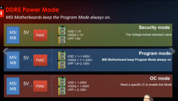
I will look over the spec, but can you tell me a little more about what manual vdimm control means? I don’t recall seeing that previously, but if it is just a bit in the spec it should be possible to change it if the ddr5 is in offline mode.
Manual vdimm control would be having the ability to change the output voltage from the pmic to the dram ICs themselves. The name can be any mishmash of vdimm, dimm vdd, dram vdd, etc.
As an example: jedec specs for ddr5 call for 1.1v output to the dram ICs at all (almost all?) jedec specified speeds/timings. XMP/EXPO profiles generally deviate from this and send 1.3v/1.35v/1.45v/etc.
On most consumer udimm motherboards you are able to change this output voltage manually, in steps of 5mv or 10mv, from within the bios. Setting this voltage would bypass what the sticks profiles’ would set themselves (you could set 1.4v in bios when the sticks only have profiles for 1.1v, for example)
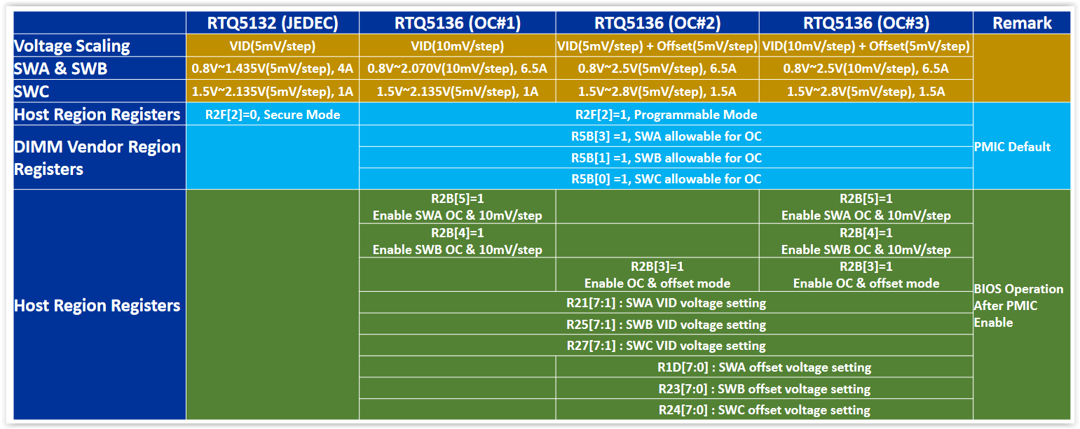
As for ‘secure enabled’, these images my help. Basically, if the dimm is in secure mode, the motherboard/bios voltage changed will have no affect. The below register seem to be specifically for Richtek but I do not know it it applies to others: