Measuring frequency modulation has become somewhat of a pain. I think the easiest thing may be to build a mini logic analyzer and sample after the first falling edge. Then we’ll read those bytes out and look for the 1->0->1 transition and count the number of time units.
Depending on how the IR carrier burst in implemented, the first and last bit of carrier may not be a full cycle. So we can wait on the first two transitions to make sure we have a good start point.
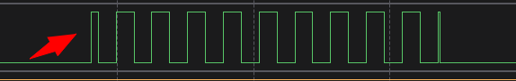
This is what the learner sees in response to the TX of the IR LED above.
move 8*32, x
wait 0 pin 0b1
wait 1 pin 0b1
loop:
in pins 1
jmp x-- loop
irq wait IRQ_NUM
The FIFO has 8x32bits, so we can put 256 samples directly in the FIFO and deal with it later.
- Wait for first transition
- Take 256 samples
- Set IRQ and wait for firmware intervention
| Frequency | 20kHz | 36kHz | 38kHz | 40kHz | 56kHz | 60kHz |
|---|---|---|---|---|---|---|
| Duration | 50us | 27.8us | 26.3us | 25us | 17.8us | 16.7us |
The learner works from 20kHz to 60kHz, so frequency measurement should be accurate over that range. Here is the duration in us for some key frequencies.
| Frequency | 20kHz | 36kHz | 38kHz | 40kHz | 56kHz | 60kHz |
|---|---|---|---|---|---|---|
| Bits @ 0.2us | 250 | 139 | 131 | 125 | 89 | 83 |
It looks like 0.2us per sample might be a good first try, giving the best resolution possible while keeping everything inside the 32*8byte FIFO.
This is the least Rube Goldberg way I can think to do this given the RP hardware.