REV10 batch 1 errors, fixes, replacements

There are two errors in REV10 batch 1. I’m sorry, it’s my fault and I’m super embarrassed. I’ll make sure we take care of everyone.

#1: A missing pin connection

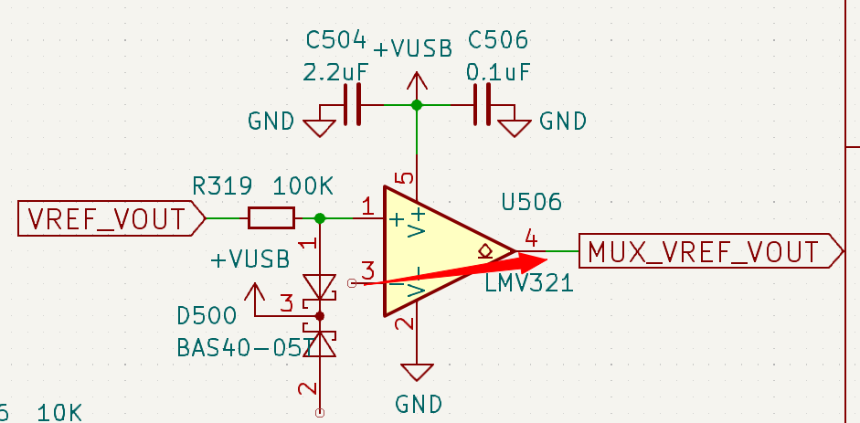
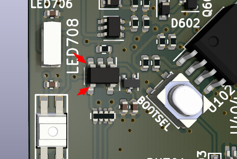
The pins of this op-amp should be connected. Without it, the Vout/Vref voltage always reads 5volts. This would be obvious, but the firmware was sampling the power supply from a second tap point without the op-amp buffer.

When you update to a “fixed” firmware, the VOUT will always read 5volts (regardless of the actual voltage on the pin).

The KiCad files were passed around a lot during the November update. I think at some point the connection was accidentally deleted/moved as part of a group select, or an old revision entered the mix. Either way, I didn’t catch it on final review.

Easy-ish fix (for some)

media_20240201_163031_8656036360333719273

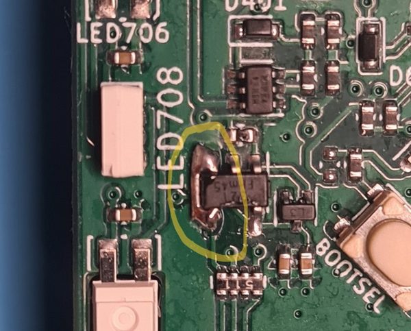
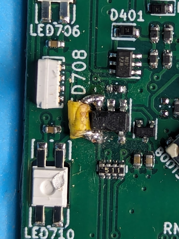
The pins are close, so it’s fairly easy to solder a connection. I bridged the gap with a small piece of through-hole resistor lead cut with fingernail trimmers.
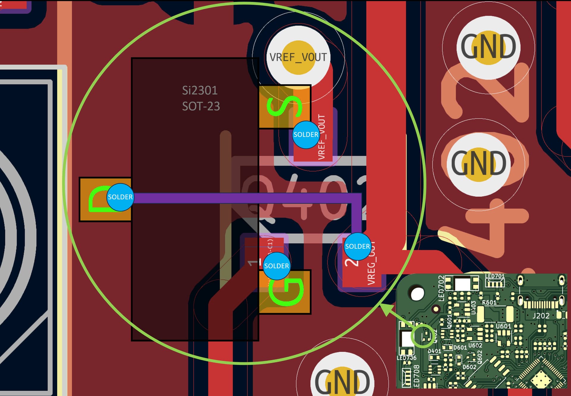
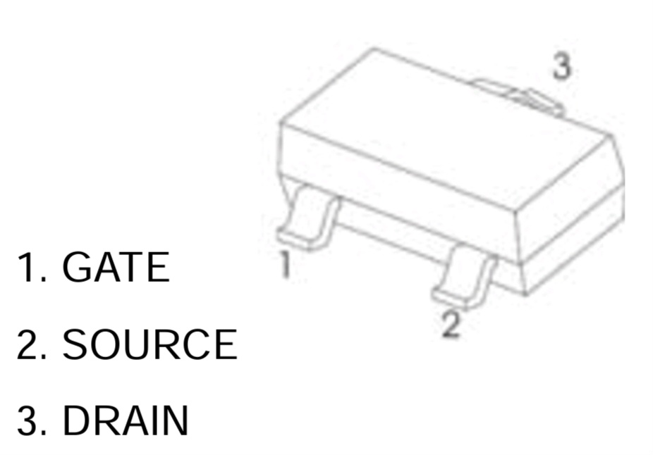
#2: Backwards PFET

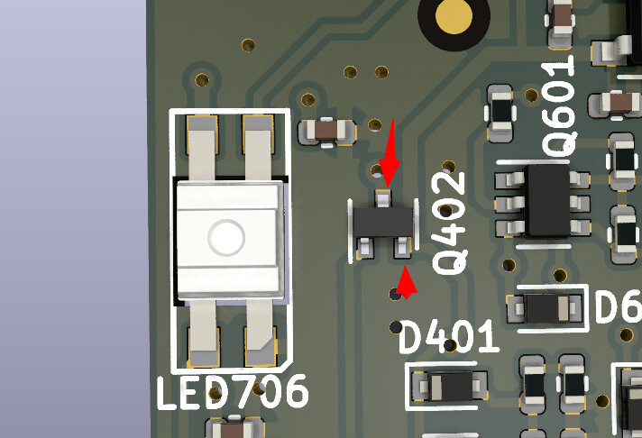
The drain and source of Q402 are swapped. It was correct in the REV8 preview board, but at some point it was mirrored. Probably when we changed to the SI2301 or the smaller SOT-523 package.

This PFET is part of the current backflow prevention circuit, a one-way valve on the output of the onboard power supply.

  • Prevents external voltage applied to VOUT/VREF pin from reaching the output pin of the adjustable voltage regulator. I’ve been told this isn’t generally a problem, but I like to keep it clean.
  • To detect conflicts between onboard and external power sources, and issue a debug alert in the terminal

The PFET is used as an ideal diode, so in this case the orientation matters and the backflow prevention doesn’t work properly.

To the best of my understanding this is not a fatal flaw. FETs are symmetrical and the drain/source is relative to the voltage applied at each and the gate. Optimizations in the component design could cause damage over time at high current/voltages when reversed, but the Bus Pirate is well under the maximums for this part.

Please chime with more info. This is far from my area of expertise, generally speaking I aim to put parts in the correct way around.

Fixes

1706800792732

  • None: ignore it with some reduced functionality (and try not to back power when the Bus Pirate isn’t connected to a USB port).
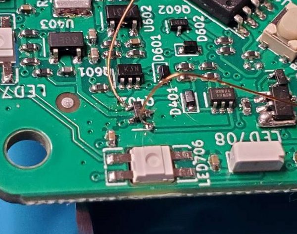
  • Deadbug the PFET. Not a pretty or easy fix for SOT-523.
  • For 10 reels minimum (~$220USD) I can have a PFET custom die bonded in the “wrong” pinout as a replacement part.

Impacted batches and what happens next

Batch 1 (shipped)

Already shipped, you may have one now.

  • If you try to fix it, please share a photo and your experience!
  • For a replacement PCB: open a support ticket and I will send a new board when they are available after Spring Festival.

Batch 2 (recalled from logistics)

Upon discovering the bugs we recalled all of batch 2 from logistics. We will contact everyone in batch 2 right now with options.

  • Ship now, attempt to fix it yourself
  • Wait for updated boards after Spring Festival (some days after February 19)
  • We’re always happy to refund an order, you can even do it yourself on the order page

Batch 3 (scheduled for Feb 19+)

A fix has been issued and PCBs are already being made. Production will resume on schedule immediately after February 19 using the updated boards.

Thank you

Thank you for checking out the Bus Pirate. I’m really sorry about this issue, especially right before a holiday when there’s little I can do to hurry things along.

Thank you to ElectronicEel on Mastodon for reporting the backwards PFET that led to a wider investigation.

4 Likes

I still didnt get the board but well I assume there is no other option then Reuse, Repurpose, Fix, DIY -aproach :laughing: And its also 0,1% more ecological friendly.

Wondering what kind of wire to use for the second fix.

2 Likes

I use enameled wire, but I really hate mine. I bought a spindle from my local shop, the only kind they had. Some can be “stripped” with a hot soldering iron, but this stuff needs to be sanded with the rough side of a nail file. I’m open for recommendations.

Enamel wire and I have a bit of a history. Once the police showed up. It was embarrassing.

1 Like

Hi Ian

The REV10 Batch 1 arrived today.
I saw the wrong places and I fear that recovery is beyond my capabilities. I can’t fix it, I can’t even see the pins :smiley:
When you can, write to me privately for instructions for a correct replacement.

Greetings
D.

No problem. It should do all the things I demo. I’m using the same. Will send you a replacement.

1 Like

Hi Ian,
Great project, I’m looking forward to trying it out! I’m in batch 2, and have raised a support request to receive the board anyway, and then fix it myself.
I was thinking of a way to fix the MOSFET issue when it arrives, and wanted to run it by you:


The idea is, to remove the SOT-523 part and discard it (since it is so tiny), and then swap to a Si2301 P-Ch MOSFET in SOT-23 package, and install it rotated 90 degrees anti-clockwise.
If that is done, then only two pins are solderable to the existing pads on the board, and then the remaining pin (which will be the Drain pin) can be attached with a tiny piece of wire (shown in purple on the diagram).
The reason I was thinking the SOT-23 part would be good, is (a) it is larger and easier to solder! and (b) I’m more likely to have that part so I don’t need to purchase it.
Here is another (maybe easier to follow) diagram of the proposed idea (if it works!):

2 Likes

Hi Ian, thank you for sharing this with us, these things happen unfortunately when you have to switch to other parts. I could probably manage the missing pin connection but the FET is so small I can barely see it.
I almost feel bad about opening a support ticket.

I am going to try and fix it myself, but would like to sign in for a replacement board. How do I open a support ticket?

1 Like

I just got my R10. I’m not sure about the deadbug mod - i.e. which pins go where. A picture would help. And we totally forgive you, Ian. It’s a very cool project and the price is reasonable, and you are doing so much to make it a success.

1 Like

Yes, that should work! What a creative solution.

2 Likes

You can click the link on your order email and open a support ticket there. It’s no problem, I want everyone to have working hardware.

3 Likes

I turned the fet 180 degrees. I soldered the top pin (3) to the right bottom pad, and pin 2 to the top pad. Then I ran a jumper wire from pin 1 to the bottom left pad.

I only did this to check before we sent more PCBs for production, I’m not actually using this board. The opamp is worth fixing, but the FET doesn’t impact anything Im working on. I’d cover the fix in a blob of hot glue if I was planning to use it.

2 Likes

Mine arrived last week, so I suspect I’ve got an affected unit. If I understand correctly:

  • Issue 1 is 100% resolved by jumping the two pins as in the first photo of the original post above
  • One can verify the fix by flashing a newer firmware and seeing that indicated Vout actually tracks as expected
  • Issue 2 sounds is basically a non-issue so long as I’m not doing anything extreme with external power, or if I only ever use internal power

What constitutes a ‘new firmware’ to check issue 1?

1 Like

Hi @mtrudel ,

Yes, that’s my take. The opamp needs to be fixed with a jumper, the latest auto build firmware has the fix that makes it obvious:

The PFET is not so important. It prevents back powering, and to some extent “protects” the adjustable vreg from voltage on its vout pin. Though better engineers said I shouldn’t bother because it doesn’t matter. I kept it because it’s simple, and it gives a way to warn users that there might be something bad going on and they should investigate. If you’re not using external voltage sources, or if you make sure not to connect them while the bus pirate is powered down, then it generally isn’t an issue.

1 Like

Fixed issue #1 (initially tried using 28ga bodge wire but your ‘clipped through-hole lead-bent-into-a-u-shape-and-tacked-down-in-place’ approach worked much better). It’s not pretty, but it works:

Confirmed that I’m seeing expected Vout values with the latest firmware.

2 Likes

That looks right! That’s the right connection

It’s my go to! I have never ending frustrations with bodge wire. A bit of resistor lead is really useful for adjacent pin repairs.

Ok so I payed the tax and recieved BusPirate I straight away opened it up to take a look and I might have overestimated my soldering skills. The elements are really tiny. And I am not sure what to do now. Waiting for some soldering accessories from ali. Like proper third hand and I will try to fix it but what if I break it? Is there a guarantee on unskilled tinkerers?

The only important bit is the jumper on the SOT-23 op-amp. That’s not too hard, just needs a glob of solder and a bit of wire or resistor lead. If you beak it I’ll send replacement.

I used a piece of jumper wire (from the breadboard kits), and put a small piece of heat-shrink tubing (which wasn’t necessary - I know). I carefully shaped and cut the wire to be the exact shape, and soldered when it fit. It wasn’t easy, but I think I got it. The second fix looks like a real challenge and I’m not sure I can do it, So the new firmware makes it obvious if I did it right?

1 Like

Yes, with the latest firmware the Vout will be stuck at 5volts without the fix.

You repair looks great!